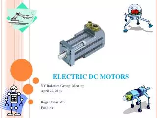
DC Motors
CHAPTER. DC Motors. 8. Instructor Name: (Your Name ). Learning Objectives. List the components of a typical starting (cranking) motor Describe how interacting magnetic fields cause the armature in an electric motor to rotate

DC Motors
E N D
Presentation Transcript
CHAPTER DC Motors 8 Instructor Name:(Your Name)
Learning Objectives • List the components of a typical starting (cranking) motor • Describe how interacting magnetic fields cause the armature in an electric motor to rotate • Explain why a starter motor draws less current as motor speed increases • List the advantages and disadvantages of a gear reduction starter motor
Learning Objectives • Measure cranking circuit resistance using the voltage drop method • Troubleshoot the cause of a no-crank problem • Disassemble a starter motor, test the internal components, and reassemble • Perform a rapid assessment of a trucks electrical system • Explain how rotational direction is reversed with a permanent magnet motor
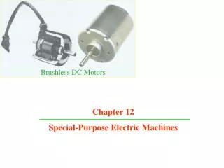
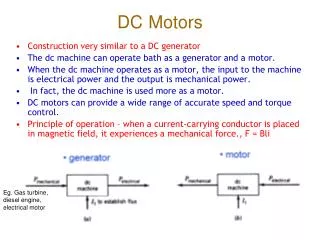
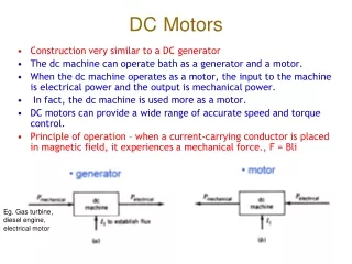
Introduction • Electric motors are used extensively on modern trucks, windshield wipers, heating and A/C, some hydraulic ABS systems • The starting or cranking motor is the largest • Electric motors convert electrical energy into mechanical energy • Almost all motors used on trucks uses brushes to contact the rotating elements, hence the name brushed DC motors
Important Facts Two magnetic fields that interact with each other combine to form a single magnetic field. If the arrows on the magnetic lines of force of both magnetic fields are pointing in the same direction, the resulting magnetic field is strengthened. If the arrows on the magnetic lines of force are pointing in opposite direction, the resulting magnetic field is weakened.
Interaction of Current Carrying Conductor in a Magnetic Field Figure 8-3(A) Current-carrying conductor placed in magnetic field causes an interaction between magnetic fields; conductor is compelled to move from strong magnetic field to weak field. (B) Current-carrying conductor formed into a loop is compelled to rotate around its axis to move from strong field to weak field.
Important Facts Conductors that are carrying current are compelled (want) to move out of a stronger magnetic field into a weaker magnetic field.
Components of a Simple Electric Motor • Armature – The conductive loop that rotates inside an electric motor • Split Ring Commutator – Provides connection to both ends of the armature loop through brushes and allow it to rotate. • Pole Shoes – Electromagnets that surround the armature. • Field Coils – Copper wire wrapped around pole shoes that create the electromagnet
Brushed DC Motor Figure 8-4 Brushed DC motor; current flow through armature reverses directions every 180 degrees of rotation.
Magnetic Field Developed By Pole Shoes Figure 8-5 Magnetic field developed by pole shoes.
Armature Windings and Commutator Segments Figure 8-6 Armature windings and commutator segments.
Cutaway View of Starter Motor Figure 8-8 Cutaway view of a starter motor.
Four Insulated Field Coils with Brushes Figure 8-11 Four insulated field coils with brushes.
Pole Shoes and Field Coil Inside Iron Housing Figure 8-12 Pole shoes and field coils installed in iron housing.
Interaction of Magnetic Fields Results in Armature Rotation Figure 8-13 Interaction of magnetic fields results in armature rotation.
Series Wound Motor Figure 8-14 Series-wound motor.
Shunt Wound Motor Figure 8-15 Shunt-wound motor.
Compound Wound Motor Figure 8-16 Compound motor.
Starter Drive Components • Pinion Gear – Small diameter gear that acts as the starter output gear • Ring Gear – Part of the engine fly wheel, pinion gear engages the ring gear to rotate the engine • One Way or Over Riding Clutch – Prevents destruction of the armature due to rapid acceleration by ring gear • Solenoid – An electromechanical device used to engage the pinion gear to the ring gear
Solenoid Figure 8-17 Solenoid with coil not energized. Figure 8-18 Solenoid with coil energized.
Shift Lever Type Drive Figure 8-19 Shift-lever-type drive.
Drive Mechanism Figure 8-20 Drive mechanism.
Roller Clutch Permits One-Way Drive Figure 8-21 Roller clutch permits one-way drive.
Crank Inhibit Circuit Figure 8-22 Crank inhibit circuit.
Gear Reduction Starter Motor Cut-Away Figure 8-23 Gear-reduction starter motor cutaway.
Testing Cranking System Resistance • Connect carbon pile resistor across starter B+ and ground terminal • Connect DMM across battery terminals • Briefly load carbon pile to 500A, note battery terminal voltage • Connect DMM across the starter B+ and ground terminal. Do not connect to carbon pile clamps. • Briefly load carbon pile to 500A, note starter terminal voltage
Testing Cranking System Resistance (continued) • Subtract the loaded starter terminal voltage from the loaded battery terminal voltage. The result is the amount of voltage that is dropped on the positive and negative cranking circuit battery cables.
Measuring Cranking System Resistance Figure 8-24 Measuring cranking circuit resistance by loading to 500A and measuring voltage drop on circuit.
Determining the Source of Excessive Voltage Drop in a Cranking Circuit • Connect carbon pile resistor across starter motor B+ and ground terminal • Connect DMM across battery positive and starter positive terminals. Do not connect to carbon pile clamps. • Briefly load carbon pile to 500A and note positive circuit voltage drop
Determining the Source of Excessive Voltage Drop in a Cranking Circuit (continued) • Connect DMM across battery negative and starter negative terminals. Do not connect to carbon pile clamps. • Briefly load carbon pile to 500A and note negative circuit voltage drop • The positive and negative circuit voltage drops should each be about half the maximum allowable voltage drop or 0.25V
Finding Source of High Cranking System Resistance Figure 8-25 Finding the source of the high cranking circuit resistance.
Basic Electrical/Electronic Diagnostic Procedure Flowchart Figure 8-29 Diagnostic flowchart.
Cranking Circuit Diagram Figure 8-30 Cranking circuit diagram.
DMM Measuring High and Low Side of Magnetic Switch During Cranking Figure 8-31 DMM measuring high and low side of magnetic switch coil during crank.
Voltage Measurements at Neutral Start Switch Figure 8-32 Voltage measurements at neutral start switch.
Starter No-Load Bench-Test Setup Figure 8-33 Starter no-load bench-test setup.
Testing For Open Field Coils Figure 8-35 Testing for open field coils.
Testing For Shorted-to-Ground Field Coils Figure 8-36 Testing for a shorted-to-ground field coil.
Testing Armature For Shorts-to-Ground Figure 8-39 Testing armature for shorted-to-ground windings.
Testing Armature For Open Circuits Figure 8-40 Testing armature for open circuits.
Energizing the Starter to Measuring Pinion Clearance Figure 8-42 Energizing the starter motor solenoid to measure pinion gear clearance.
View Looking into a Single Loop Armature Figure 8-46 View looking into a single-loop armature.
Armature Rotating Due to Magnetic Field Interaction and Commutation Figure 8-47 Armature rotating due to magnetic field interactions and commutation.
CEMF in Stationary Motor and Motor at Full Speed Figure 8-48 CEMF with motor stationary (top) and motor rotating at full speed (bottom) and the effect on current drawn by the motor.
Starter Solenoid Pull-In and Hold-In Windings Figure 8-50 Starter solenoid hold-in and pull-in windings.
Summary • Electric motors convert electric energy into mechanical energy. Most electric motors used on trucks are a brushed DC-type motor. • A brushed DC motor has spring loaded brushes that make contact with the commutator segments. The commutator segments are attached to loops of wire that make up the armature assembly. The armature is the rotating component of the starter.
Summary (continued) • The pole shoes are the stationary electromagnets bolted to the motor frame. Field coils surround the pole shoes. Current flow through the field coils causes the pole shoes to be magnetized. This set up a stationary magnetic field. The stationary magnetic field interacts with the magnetic field surrounding the armature windings. The interaction causes areas of weak and strong magnetic fields inside the motor. The armature rotates to escape the strong fields.
Summary (continued) • The commutation process describes the reversal of current flow through the armature winding at just the right time to keep the armature in a location of strong magnetic field. The current reversal causes the armature to continually rotate in an attempt to escape the strong magnetic fields.
Summary (continued) • Counter-electromagnetic force (CEMF) is the voltage that is induced in the armature windings as they pass through the magnetic fields set up by the pole shoes. The CEMF acts as a series-opposing voltage to the battery voltage. The CEMF increases as the motor speed increases. This causes the current drawn by the starter to decrease as the motor speed increases. The highest level of current draw is when the starter motor is stationary.
Summary (continued) • The starter motor assembly contains the pinion gear. The drive assembly assembly causes the pinion gear to be meshed with the engine ring gear when the motor solenoid is energized. The drive assembly contains a one-way clutch that permits the starter motor to drive the engine but prevent the engine from driving the starter motor.