Download

1 / 16
170 likes | 570 Vues
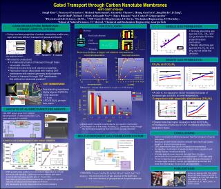
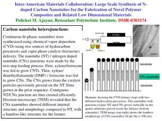
Aligned Multiwalled Carbon Nanotube Membranes. Science , Jan. 2004; Vol. 303. no. 5654, pp. 62 - 65 DOI: 10.1126/science.1092048. Bruce J. Hinds, Nitin Chopra, Terry Rantell, Rodney Andrews, Vasilis Gavalas, Leonidas G. Bachas. Yihong Liu March, 23 rd , 2009. Outline.

E N D
Aligned Multiwalled Carbon Nanotube Membranes Science, Jan. 2004; Vol. 303. no. 5654, pp. 62 - 65DOI: 10.1126/science.1092048 Bruce J. Hinds, Nitin Chopra, Terry Rantell, Rodney Andrews, Vasilis Gavalas, Leonidas G. Bachas Yihong Liu March, 23rd, 2009
Outline • What is Aligned Multiwalled Carbon Nanotube Membranes? • Signification. • How to make it? • 4 ways to confirm it • electron microscopy, electrical conductivity, gas flow, and ionic transport. • application in chemical separations Yihong Liu
h What is it? • An array of aligned carbon nanotubes was incorporated across a polymer film to form a well-ordered nanoporous membrane structure. Dispersion of metal nanoparticles for aligned carbon nanotube arrays Hiroki Ago et al. APP. PHY. LET, V 77, 1, (July 2000) Yihong Liu
Signification • chemical selectivity • chemical separations • drug delivery • wastewater remediation • Matching of pore size to that of the target molecules • challenge in the size range of 1~10nm. Yihong Liu
Carbon nanotube growth • Co nanoparticles are well separated with a certain distance. • Co nanoparticles aggregated and formed Co clusters • pyrolytic reaction occurs at the tip of the cluster • Nanotube size is set by the diameter of the catalyst particle. Dispersion of metal nanoparticles for aligned carbon nanotube arrays Hiroki Ago et al. APP. PHY. LET, V 77, 1, (July 2000) Yihong Liu
Fabricated Membrane 2.5μm CNT array 50μm Fabrication • Impregnated with PS (A 50% solution of polystyrene and toluene was spin-coated.) • Dried in vacuum at 70°C for 4 days • Hydrofluoric acid was used to remove from the substrate • 5- to 10-µm thickness. Yihong Liu
Fabricated Membrane 2.5μm CNT array 50μm Processing scheme 6 (±3) x 1010 tips per cm2 Yihong Liu
H2O plasma etching Plasma Etching for Purification and Controlled Opening of Aligned Carbon Nanotubes Shaoming Huang and Liming Dai J. Phys. Chem. B, 2002, 106 (14), 3543-3545 Yihong Liu
Electron microscopy 200nm TEM image of CNT tips after H2O plasma oxidation. 70% etched away. 10nm 6 (±3) x 1010 tips per cm2 Yihong Liu
electrical conductivity • conductivity from top to bottom of the membrane • 35.2W–1cm–1 0.32W–1cm–1 • Au film contacts, a 4-point probe • Measure sheet resistance in-plane conductivity • Reduced in-plane conductivity would be expected, because neighboring CNTs only touched each other with the modest tortuosity. Yihong Liu
Gas flow • Molar flux Na =eDk(P1 – P2)/RTLa • the porosity 0.027, a tortuosity 1.10 (±0.05), L film thickness 5 (±1) µm. • Knudsen diffusion Dk = 0.97r (T/Ma)1/2 r mean pore radius 7.5 (±2.5) nm, Ma molecular weight (N2) • Knudsen diffusion, the gas-molecule mean free path is limited by pore radius. Measured, from curve fit: 2.6 µmol/(m2 s Pa) Calculated, from theory: 2.4 (±1.9) µmol/(m2 s Pa) Yihong Liu
P P0 N2 Pore size • N2 desorption at 77 K • CNT inner-core diameters (6 to 10 nm) without embedded polymer • Observed mean pore diameter of 7.5 (±2.5) nm Yihong Liu
Ionic transport • Ru(NH3)63+ flux, 0.07 µmol.cm–2h–1; • Treat with hydrochloric acid (HCl) for 24 hours, flux increases to 0.9 µmol/cm–2h–1; • presumably by dissolving excess Fe not removed by the plasma process. • In a control experiment, membranes without H2O plasma treatment did not show ionic transport. • The ionic diffusion coefficient D 2.2 (±0.9) x 10–6cm–2s–1; • Near the bulk aqueous-solution diffusion 7 x 10⁻⁶cm–2s–1; • Only modest interaction of the ion with the CNT tip and the core. Yihong Liu
Gatekeeper-controlled chemical separations • Ru(NH3)63+ flux through a CNT membrane structure after HCl treatment (circles), • biotin functionalization (squares), • streptavidin coordination with biotin (triangles). • Source solution, 5 mmol Ru(NH3)63+ , • analyte volume 0.4 ml, • membrane area,0.028 cm2. Reduced by a factor of 5.5. Further reduced by a factor of 15. Yihong Liu
Summary • Aligned carbon nanotube membranes fabrication, confirmation, and application. • Over 200 citations for following and related research. • Eg. Ion transport, nano-fluidics; • Sub-2-nm carbon nanotube pores. Yihong Liu