Download
1 / 28
280 likes | 380 Vues
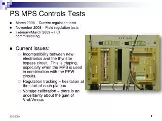
PS MPS Controls Tests. March 2008 – Current regulation tests November 2008 – Field regulation tests February/March 2009 – Full commissioning Current issues:

E N D
PS MPS Controls Tests • March 2008 – Current regulation tests • November 2008 – Field regulation tests • February/March 2009 – Full commissioning • Current issues: • Incompatibility between new electronics and the thyristor bypass circuit. This is tripping, especially when the MPS is used in combination with the PFW circuits. • Regulation tracking – hesitation at the start of each plateau • Voltage calibration – there is an uncertainty about the gain of Vref/Vmeas
PS MPS Controls Upgrade Status • Tests during the past two weeks: • Voltage gain measured to first order • PHASEBACK feature added • B-Train time windows adjusted by B-train people • Voltage gain • Follow up tests at 1kV with direct DVM measurement will be done tomorrow • Source of voltage measurement offset (-7V) will be hunted • PHASEBACK • First version of adaptation card was unstable • Cleaned up version worked fine
But did PHASEBACK solve the bypass thyristor trips? When running the PFWs with the TSTLHC25 cycle a thyristor bypass trip was almost immediate (less than 5 cycles) With the new card we still had the same problem!
The problem is the Bref function The Bref function had a 480ms tail with Bref = 0 The remnant field is ~20G so the B-loop demands more and more negative voltage For some reason this tripped the bypass thyristor – not sure why Removing the tail allows PHASEBACK to be activated immediately after the ramp down – no more trips Software now prevents this case being requested by the users
Is the V-loop helping? We saw a variation in response time for the Vmeas when asking for the initial openloopVref(4-8ms) V-loop bandwidth is ~100Hz with a 2nd order response
The V-loop wins… +9kV Voltage Current • We will definitely use the V-loop to remove dependence on the current and to remove subtle non-linearities • But we will do one more set of tests with direct control of firing • Measurement of max voltage available for different currents • We want to know the full 2-Quadrant envelope -9kV
For the shortest ramp down: +9kV Voltage Current We will lose this potential voltage! -9kV • I will try PHASEBACK during the ramp down • By aborting function early when the voltage starts clipping the PHASEBACK will demand the maximum possible negative voltage all the way down FGC limits are linear:
Regulation Our target is +/-0.3G maximum error This is not easy! Magnet saturation reduces inductance by 50% Hysteresis is up to 50G Remnant field varies by many Guass Accelerations are ~+/-500 kG/s2
Example – with saturation (13kG) • Martin will add a linearisation stage to suppress the effect of the change in inductance • Note: • Regulator is a PI at the moment • Tests of PII haven’t yet improved the regulation • Period is 5ms – we would like to reduce to 3ms if possible • Model of voltage source is not yet final – hopefully this will help the transients • Hysteresis is more difficult – we hope it doesn’t need to be considered