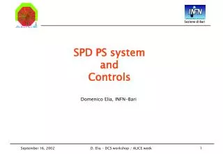
SPD PS system and Controls
SPD PS system and Controls. Domenico Elia, INFN-Bari. SPD CS. COOLING. LV. PILOT. HV. LV PS. Cfg Params. I, V, T. HV Crate. VR Boards. SPD CS architecture (1). The SPD Control System: Control and Monitoring of HV PS Control and Monitoring of LV PS and regulators

SPD PS system and Controls
E N D
Presentation Transcript
SPD PS system and Controls Domenico Elia, INFN-Bari D. Elia - DCS workshop / ALICE week
SPD CS COOLING LV PILOT HV LV PS Cfg Params I, V, T HV Crate VR Boards SPD CS architecture (1) • The SPD Control System: • Control and Monitoring of HV PS • Control and Monitoring of LVPS • and regulators • Control of Config. Params and • Monitoring of LV, T (PILOT) • Control and Monitoring • of COOLING system D. Elia - DCS workshop / ALICE week
SPD CS architecture (2) PVSS main VME - DAQ SPD CS LV, T monitor Data + I, V, T Set config params Control action on VR Ethernet JTAG Cfg Params JTAG VR ctrl Cooling SPD VR boards LV PS HV PS Interlock 2 1 D. Elia - DCS workshop / ALICE week
CAEN SY 1527 LAN /OPC RS-232C RS-232C 80 V Analog PS master 5V ~ 4A Digital PS slave Analog supply Bias 1 5V ~ 3A Bias 2 Digital supply SPD PS control: prototype I LabVIEW application CAEN OPC Server Regolator Board and Control elec. ST L4913Parallel scheme for Analog supply UART RS-232C Ladder 1 ST L4913Single scheme for Digital supply Ladder 2 D. Elia - DCS workshop / ALICE week
Steps towards prototype II • Design of the new VR board: • full set of LV supplies for 1 half-stave (7 voltage regulators) • fine tuning of VRs output via on-board DACs • output voltages and currents available via on-board ADCs • control logic implemented via on-board FPGA • control operations by JTAG • Implementation of the supervisory control (PVSS): • control of HV/LV supplies via PVSS • link of PVSS to JTAG controller • full integration of HV/LV/VR-boards D. Elia - DCS workshop / ALICE week
Long term planning (1) • FEE: • - definition of Pilot Data frame • - definition of DCS part of Router module • - definition of interface between Router and ALICE-DCS • - prototype chains for I,V monitoring • - tests of Analog Pilot (I,V,T) and Digital Pilot • - prototype of full FEE monitoring chain with Router • Interlocks: • - definition of interlock strategy • - tests with Analog Pilot • - design of interlock box • - integration with ALICE Safety System • - full working prototype ( In collaboration with P. Chochula ) D. Elia - DCS workshop / ALICE week
Long term planning (2) • Power suppies and VR: • - tests and choice of HV/LV PS • - prototype of VR board • - interface between VR and DCS • - integration with interlock and FEE monitoring system • Temperature monitoring: • - prototype with PT1000 daisy-chain • - choice of sensors • - design of dedicated bus • - test with Analog Pilot • - interfacing with DCS • Database, 6. Cooling D. Elia - DCS workshop / ALICE week