Download
1 / 32
320 likes | 579 Vues
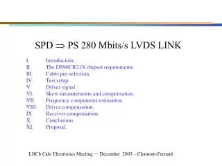
SPD PS 280 Mbits/s LVDS LINK. Introduction. The DS90CR21X chipset requirements. Cable pre-selection. Test setup. Driver signal. Skew measurements and compensation. Frequency components estimation. Driver compensation. Receiver compensation. Conclusions Proposal.

E N D
SPD PS 280 Mbits/s LVDS LINK • Introduction. • The DS90CR21X chipset requirements. • Cable pre-selection. • Test setup. • Driver signal. • Skew measurements and compensation. • Frequency components estimation. • Driver compensation. • Receiver compensation. • Conclusions • Proposal. LHCb Calo Electronics Meeting – December2003 –Clermont-Ferrand
I. Introduction. • This presentation has two main purposes: • Summarize the requirements of the chipset and the constraints of the cables. • Report the test of different possible solutions to cable skew and to cable attenuation done at Barcelona by Albert Comerma, Jacques Lefrançois and David Gascon. • The solutions presented here assume that LVDS driver is working on standard conditions. • Discussion to choice the best solution has different constraints because schema proposed by Jacques Lecoq is able to increase the signal beyond the specifications of LVDS.
II. The DS90CR21X chipset requirements (I). • 21 bits to 3 data pairs + 1 clock pair. • Differential output voltage 250mV (min), 290 (typ) and 450 mV (max) on 100 . • Differential input threshold: • High: +100mV. • Low: -100mV. • Data rate: 40 Mbit/s x 7 = 280 Mbit/s per pair. • Qualified for radiation. • No pre-emphasis. • No DC balance.
II. The DS90CR21X chipset requirements (II). • National Application note 1059. • RxCLK IN during present cycle generates strobes to sample data next cycle. • Each strobe is based on previous ones. • Strobes are resynchronized with the rising clock edge for each new clock cycle.
II. The DS90CR21X chipset requirements (III). • Receiver skew margin (RSKM) definition according to National Application note 1059. RSKM is the margin for data sampling at receiver inputs. This number is based on the pulse position (Tppos) and strobe position (Rspos) characteristics of the device. : • c: represents the setup and hold times for the receiver relative to the ideal strobe position (Rspos max and Rspos min). • d: is the variation of transmitter pulse position from ideal (Tppos max – ideal and ideal - Tppos min) . • e: is the cable skew. • f: is the clock jitter. • m: is the remaining margin for data sampling: m=rskm – (e+f). • For the DS90CR21X chipset RSKM=490 ps at 40 MHz. • Since bit width is 3.57 ns, time opening of an eye diagram should be 2.59 ns. • But: which is the signal level required at this point? • If it is higher than the threshold: this requirement will not be fulfilled after a few meters of cable?.
III. Cable pre-selection (I). • Several factors like skin effect and dielectric losses introduce a dependence of the cable parameters (R,L,C,G) on frequency. • Therefore cable attenuation and transmission velocity depend also on the frequency and signal shape is changed. • The 2 main parameters to take into account for cable choice would be attenuation and skew (which is crucial according RSKM requirements of Receiver). • The 4 twisted pair cables used for LAN (Ethernet) are the best candidates for price and availability. • Several standards might be considered: cat5, cat6 and cat7. Main differences are requirements on attenuation, skew, crosstalk and return losses. • Other important distinction is between rigid and multifilar cables. First ones are used for vertical cabling on LAN and have smaller attenuation than the multifilar ones, used for short patch cables.
III. Cable pre-selection (II). • Cables of category 5e (enhanced category 5), 6 and 7 will be tested since all of them might fulfil attenuation requirements. • Rigid cables are chosen because attenuation of patch cable would be too high for standard LVDS signal. For example, the nominal attenuation of a rigid cat 7 of Infra+ (MNCGM800) at 100MHz and after 25m is 1.66 while for its multifilar counterpart (MNC4x1PF600) is 2.33. The specified maximum skew is also smaller for the rigid one: <5 ns/100m versus 12 ns/100m for the flexible. • The manufacturers only specify and upper limit for skew between pairs and for all the categories this limit is higher than the RSKM < 490 ps requirement. • Several rigid cables will be tested: • Cat5e (MNCep800) from Infra+ • Cat6 from Infra+. • Cat7 (MNCGM800) from Infra+ • Cat7 (LANMark cat7) from Nexans (Alcatel). • Only the cat5e allows to mount RJ45 male connectors, other rigid cables will be connected through RJ45 female connectors and short (10 cm) cat5e patch cables for the test.
V. Driver signal (I). • Output signal at the DS90CR125 over 100 .
V. Driver signal (II). • The dynamic output impedance of the driver considered as a current source is studied. • According the table levels are right, just the voltage is almost linear with resistance, except for 200 where small attenuation is seen. • In the signal shape for a load of 200 a fast slope up to 400 mV is observed, followed by a slower rising (about 5ns) .
VI. Skew measurement and compensation (I). • Maximum difference between pairs (skew) has been measured for the 4 cable types tested and for different lengths, conclusions are: • Only skew of the cat7 cable from Nexans will be smaller than RSKM, but even on that case some compensation is needed to keep some safety margin to cover the clock jitter or the distortion of the signal shape after 25m of cable.
VI. Skew measurement and compensation (II). • Cat5e: • First, cat5e cable is cut in the middle part and the fastest pair is crossed with the slowest, and second fast with the second slow. The skew is reduced to 25ps/m that is to about 600 ps which is not enough. • Then, cable is cut in four pairs and all pairs are crossed. The remaining skew is 34 ps for a 15m cable, 210 ps for a 20 m cable and 126 ps for a 25m cable. • The skew for a 20m cable is higher than the skew for 25 m cable, this probably means than production tolerances start to play some role. • Cat6: cable is cut by the middle and the fastest pair is crossed with the slowest, and second fast with the second slow. The remaining skew is 8,5 ps/m, that is 212,5 ps which is enough. • Cat7 (Infra+): cable is cut by the middle and the fastest pair is crossed with the slowest, and second fast with the second slow. The remaining skew is 45 ps for a 15 m cable, 120 ps for a 20 m cable and 92 ps for a 25 m cable. • Cat7 (Nexans): cable is cut by the middle and the fastest pair is crossed with the slowest, and second fast with the second slow. The remaining skew is 50 ps for a 25m cable.
VII. Frequency components estimation (I). • Method described in “Time domain compensation of cable induced distortions using passive filters for the transmission of fast pulses” G. Amsel et alt., The Review of Scientific instruments, vol. 42, num. 8, august 1971. • Signal after cable r(t) is considered to be the convolution of an “ideal” fast and arbitrary signal b(t) and the cable effects r(t): r(t)=b(t)*h(t). • h(t) is approximated by several exponential decays. • On that case it is possible to calculate the inverse transfer function of cable load effects: . • It can be realized using a passive filter using a finite number of elements. • To estimate the filter parameters the step response is measured.
VII. Frequency components estimation (II). • The step response for 4 types of cable tested has been fitted to obtain a first order compensation: • The filter parameters can be common for all the cables at first approximation, according to the fit the DC gain of the filter should be around 0,88 and the zero time constant about 20 ns.
VIII. Driver compensation (I). • Attenuates the DC and low frequency components. • Partially adapts the driver . • According to previous considerations zero time constant should be 24 ns and DC gain about 0,88, this results on R=714 and L=17µH. It is not possible to implement such a big inductor with enough quality (resonance frequency > 250 MHz). Zero time constant: L/R
VIII. Driver compensation (II). • Before analyzing the response of several filters an eye patter for a 25m cat5e cable without compensation is shown. • The pseudo-random test pattern is generated using a IEEE standard frame in parallel for 5 bits and mixing faster signals (20 MHz and 8 MHz) from other sources.
VIII. Driver compensation (III). • The bigger inductance available is used. (Cat5e Infra+ 25m) • L = 3.6 µH and R = 150 . • DC gain = 0.6 and zero time constant = 24 ns. • Eye time opening at ±100 mV: 900 ps. • Good results: attenuation is equalized and also the phase is improved. Some overshoot.
VIII. Driver compensation (IV). • Trying to increase the time constant.(Cat5e Infra+ 25m) • L = 3.6 µH and R = 100 . • DC gain = 0.5 and zero time constant = 36 ns. • Eye time opening at ±100 mV: -. • Bad results.
VIII. Driver compensation (V). • Inductance is reduced to try to compensate better high frequency components.(Cat5e Infra+ 25m) • L = 1.8 µH and R = 150 . • DC gain = 0.6 and zero time constant = 12 ns. • Eye time opening at ±100 mV: 1240 ps. • Improvement in time opening. Less overshoot.
VIII. Driver compensation (VI). • Increasing a little bit the inductance and decreasing attenuation.(Cat5e Infra+ 25m) • L = 3.6 µH and R = 200 . • DC gain = 0.666 and zero time constant = 18 ns. • Eye time opening at ±100 mV: 1480 ps. • Good results.
VIII. Driver compensation (VII). • Trying to decrease the time constant and the attenuation. (Cat5e Infra+ 25m) • L = 1.8 µH and R = 240 . • DC gain = 0.7 and zero time constant = 9 ns. • Eye time opening at ±100 mV: 1280 ps. • Good results, but seems to be better a slower time constant.
VIII. Driver compensation (VIII). • Trying to increase the time constant and to keep the attenuation. (Cat5e Infra+ 25m) • L = 3,6 µH and R = 240 . • DC gain = 0.7 and zero time constant = 18 ns. • Eye time opening at ±100 mV: 1520 ps. • Good results, but seems to be better a slower time constant.
VIII. Driver compensation (IX). • Eye diagram for the configuration (L = 3,6 µH and R = 240 : DC gain = 0.7 and zero time constant = 18 ns) for all cable types. Cat 5e 25m Cat 6 25m Cat 7 Infra+ 25m Cat 7 Nexans 25m
VIII. Driver compensation (X). • Compensation reported on “Study of LVDS Serial Links for the ATLAS Level-1 Calorimeter Trigger”, C. Anagnostou et alt., LEB-2000is also studied. • Parameters are L =100 nH and R = 100 : DC gain = 0.5 and zero time constant = 1 ns. • It is not correct for 25m and also for 15m is not optimal unless some balancing code is used for data. Cat 5e 15m Cat 5e 25m
VIII. Driver compensation (XI). • The reception of a 1 HOT test pattern has been tested for all the cables. • Compensation parameters are L = 3.6 µH and R = 150 . • Clock frequency is increased until errors appear.
IX. Receiver compensation (I). • Input impedance must be 100 at any frequency to adapt the cable. • Attenuates the DC and low frequency components. Zero time constant:
IX. Receiver compensation (II). • First trial is to emulate the emitter filter parameters that work properly: zero time constant: 15 ns and DC gain= 0.6 • R1=250, R2=33, C=470pF and L=2.5H . • Cat5e Infra+ 25m • No significative reflections. • Step response shows a big improvement on rise time but also overshoot. Reflection after 2x25m (200ns) is < 5% Step response (C1 filter input and C3 filter output)
IX. Receiver compensation (III). • First trial is to emulate the emitter filter parameters that work properly: zero time constant: 15 ns and DC gain= 0.6 • R1=250, R2=33, C=470pF and L=2.5H . • Cat5e Infra+ 25m. • Eye time opening at ±100 mV:- • Further tunning is needed.
IX. Receiver compensation (IV). • Second trial trying to decrease overshoot and improve high frequency response: zero time constant: 9.5 ns and DC gain= 0.71 • R1=360, R2=20, C=470pF and L=2.5H • Cat5e Infra+ 25m • No significative reflections. • Step response shows slower rise time with no overshoot. Reflection after 2x25m (200ns) is < 1% Step response (C1 filter input and C3 filter output)
IX. Receiver compensation (V). • Second trial zero time constant: 9.5 ns and DC gain= 0.71 • R1=360, R2=20, C=470pF and L=2.5H . • Cat5e Infra+ 25m. • Eye time opening at ±100 mV: 1160 ps • Good results, but the equalization is not completely perfect.
X. Conclusions • It is not clear how to translate the RSKM < 490 ps requirement to parameter of the eye diagram: levels required are 0 or ±100mV? Comments… • Skew can be compensated with 3 pair crossings (all the possible combinations) for cat5e and with a single crossing for cat6 and cat7 down to <200ps for a 25 cable. • The attenuation and shape distortion of all categories can be compensated with passive filters provided that rigid cables are used. • The simple driver compensation achieves a time opening at ±100mV for a 25m cable of 1.5 ns. • The receiver compensation achieves a time opening at ±100mV for a 25m cable of 1.15 ns. • VHDL code for a Cyclone FPGA being developed to implement a BER test. • A test should be done with the full 64 channel system when a final solution is taken before freeze the design of SPD VFE and PS FE cards ... (?)
XI. Proposal: Baseline solution. • A baseline solution is proposed for a scenario where LVDS driver is used on the standard way and DC level shift is done in SPD VFE between the ASIC and the serializer using PIN diodes. Therefore, what is proposed here depends on the final choice between this and the solution consisting on shift and amplify the LVDS signal in the link. • Since each VFE board has 4 serializers and 4 cables, the proposal to deal with skew would to use the first pair of each cable for the first serializer, the second pair for the second serializer and so on. This assumes that production tolerances are low enough so the skew between the same pair of different cables is low enough (<200 ps) (Infra+ has no data but agrees to perform some tests on cable sample). • The baseline solution would be to use cat5e since is cheaper, less rigid than cat 6 and cat7 and it is possible to mount RJ45 male connectors. • There around 50 x (4 +1) cables of 25 m for SPD, this makes possible to measure the skews and group the cables. This procedure could be more efficient if PS cables (50 x (16 + 1)) were also included in the test. On that case both cables should be of same type, and for this scenario this would mean to use the rigid cat5e. • If the production tolerances are too high (and the grouping is not effective) a backup solution would be to use cat6 or cat7 by either using female RJ45 plus small cat5 patch cables either by soldering the cables to VFE board and to the piggy back board.