焊 接 (Welding)
焊 接 (Welding). 目的 : 結合兩個或數個工件成一體。 期望經焊接後之組件能夠符合實際 應用上之要求 : (1) 強度、韌性、延性, (2) 耐腐蝕, (3) 耐高溫 3. 應用 : 機械結構件、航空零件、船體、 儲油槽、天然氣槽. 焊接相關專業領域. 1. Fusion Zone: T > T M (Melting & Solidification) – 凝固理論 2. Heat Affected Zone: T > T C

焊 接 (Welding)
E N D
Presentation Transcript
焊 接 (Welding) 目的: • 結合兩個或數個工件成一體。 • 期望經焊接後之組件能夠符合實際 應用上之要求: (1) 強度、韌性、延性, (2) 耐腐蝕, (3) 耐高溫 3. 應用: 機械結構件、航空零件、船體、 儲油槽、天然氣槽
焊接相關專業領域 1. Fusion Zone: T > TM (Melting & Solidification) – 凝固理論 2. Heat Affected Zone: T > TC TC:A critical temperature above which mechanical and/or physical properties of the welding alloys will change – 熱處理原理(但程序或溫度變化較激烈) 3. Base Metal: T < TC (No changes in both metallurgical and mechanical properties)
Fig26-12 26-12
Fusion Weld Zone Figure 29.1 Characteristics of a typical fusion weld zone in oxyfuel gas and arc welding. See also Figs. 27.16 and 28.14.
Fig26-10 26-10
4. • 溫度及熱傳分析 • 顯微組織分析 • 焊接參數 • 焊料 • joint 設計 • 應力分析
1. Thermal analysis 瞭解焊件上任何一點(A)在焊接過程中之溫度變化曲線 – Thermal cycle 2. Effects of welding parameters on the thermal cycle of HAZ • Welding voltage, E • Welding current, I • Travel speed, S • Preheat temperature • Alloy composition • Section thickness of the workpiece Hi (Heat input ) = (E x I) / S
Factors affecting the microstructures and properties of fusion zone • Composition of the filler rod (selection of the filler material) • % dilution • Solidification cooling rate
Welding Design • Joint design • Weld type • Stress analysis • Welding Methods • Inspection & Testing (destructive and non-destructive) Destructive: 拉伸試驗、衝擊試驗、疲勞試驗…。 Non-destructive: 超音波探傷、X光探傷、磁粉探 傷…。
Fig. 26-6 26-6
Multiple Pass Deep Weld Figure 27.6 A deep weld showing the buildup sequence of individual weld beads.
Distortion After Welding Figure 29.10 Distortion of parts after welding: (a) butt joints; (b) fillet welds. Distortion is caused by differential thermal expansion and contraction of different parts of the welded assembly.
Incomplete Fusion Figure 29.6 Low-quality weld beads, the result of incomplete fusion. Source: American Welding Society.
Discontinuities in Fusion Welds Figure 29.7 Schematic illustration of various discontinuities in fusion welds. Source: American Welding Society.
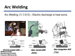
Welding Methods 1. Electrical: Resistance welding Induction welding Electroslag welding Electron beam welding Arc welding Shielded metal arc welding (SMAW) Gas metal arc weldind (GMAW) Gas tungsten arc welding (GTAW) Plasma arc welding (PAW) Submerged arc welding (SAW))
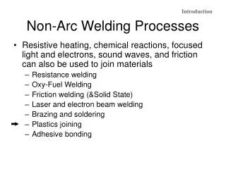
Welding Methods 2. Mechanical: Friction, Ultrasonic, etc. 3. Chemical: Oxy – Acetylene welding, Thermit reaction 4. Optical: Laser beam welding 5. Solid State: Diffusion bonding
1. Resistance Welding Processes 一、 Electrical • Resistance spot welding • Resistance seam welding • Projection welding Mass production
Fig28-4 28-4
Resistance welding R (resistance): areas to be controlled 1. Contact resistance between electrode and workpiece. 2. The resistance of workpiece itself. 3. Contact resistance between workpieces (希望電阻集中在此處). 4. The resistance of electrode itself.
electrode workpiece
Resistance Spot Welding Figure 28.5 (a) Sequence in resistance spot welding. (b) Cross-section of a spot weld, showing the weld nugget and the indentation of the electrode on the sheet surfaces. This is one of the most commonly used process in sheet-metal fabrication and in automotive-body assembly.
Resistance Seam Welding Figure 28.9 (a) Seam-welding process in which rotating rolls act as electrodes. (b) Overlapping spots in a seam weld. (c) Roll spot welds. (d) Resistance-welded gasoline tank.
Fig28-8 28-8
Resistance Projection Welding Figure 28.11 (a) Schematic illustration of resistance projection welding. (b) A welded bracket. (c) and (d) Projection welding of nuts or threaded bosses and studs. Source: American Welding Society. (e) Resistance-projection-welded grills.
Spot Welding Example Figure 28.8 Robots equipped with spot-welding guns and operated by computer controls, in a mass-production line for automotive bodies. Source: Courtesy of Cincinnati Milacron, Inc.
1.2 High frequency resistance welding (高週波電阻焊接)` Frequency:200KHz ~ 450KHz Skin effect:電流集中在表面之程度 Freq.
High-Frequency Butt Welding Figure 28.10 Two methods of high-frequency butt welding of tubes.
2. Electroslag welding (電熱熔渣焊接) 原理: Electrode is fed into a molten slag pool. An arc is drawn initially but is then snuffed out by the molten slag, and the heat of fusion is provided by resistance heating in the molten slag. Suitable for thick section welding
Electrogas Welding Figure 27.11 Schematic illustration of the electrogas welding process. Source: American Welding Society.
Fig28-21 28-21
Equipment for Electroslag Welding Figure 27.12 Equipment used for electroslag welding operations. Source: American Welding Society.
3. Electron beam welding (電子束焊接) • Heat Source A focused beam of high-velocity electrons which impinge on the workpieces. 動能 (kinetic energy) → 熱能 (heat) • Equipment An electron gun (電子槍) → Generate electrons → Focus them into a beam (聚焦成一電子束) → Accelerate them to a very high speed (加速)
Some data: • Accelerating voltage: 30 ~ 175 kV • Speed: 0.1 ~ 0.7 光速 • Beam current: 50 ~ 100 mA • Beam spot size: 0.25 ~ 0.75 mm
Degree of Vacuum (in operation) High Vacuum --- 10-3~ 10-6 torr Medium Vacuum --- 10-3 ~ 25 torr Non-Vacuum --- Atmosphere (760 torr) (1 torr = 1 mmHg)
Fig28-22 28-22
Advantages: 1. Max. weld penetration (H/D: 25/1) 2. Minimum weld width (HAZ) 3. Minimum weld shrinkage in HAZ and workpieces 4. Maximum weld purity
Disadvantages: 1. Equipment costs are high 2. Chamber size limits the size of workpieces 3. Production rate is low
Fig28-23 28-23
Tab28-4 TABLE 28-4
(a) (b) 1. Friction Welding Figure 28.3 (a) Sequence of operations in the friction welding process: (1) Left-hand component is rotated at high speed. (2) Right-hand component is brought into contact under an axial force. (3) Axial force is increased; flash begins to form. (4) Left-hand component stops rotating; weld is completed. The flash can subsequently be removed by machining or grinding. (b) Shape of fusion zone in friction welding, as a function of the force applied and the rotational speed.