Download
1 / 17
170 likes | 310 Vues
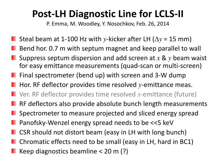
Post-LH Diagnostic Line for LCLS-II P. Emma, M. Woodley, Y. Nosochkov, Feb. 26, 2014. Steal beam at 1-100 Hz with y -kicker after LH ( D y = 15 mm) Bend hor. 0.7 m with septum magnet and keep parallel to wall

E N D
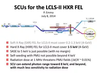
Post-LH Diagnostic Line for LCLS-IIP. Emma, M. Woodley, Y. Nosochkov, Feb. 26, 2014 • Steal beam at 1-100 Hz with y-kicker after LH (Dy = 15 mm) • Bend hor. 0.7 m with septum magnet and keep parallel to wall • Suppress septum dispersion and add screen at x & y beam waist for easy emittance measurements (quad-scan or multi-screen) • Final spectrometer (bend up) with screen and 3-W dump • Hor. RF deflector provides time resolved y-emittance meas. • Ver. RF deflector provides time resolved x-emittance (future) • RF deflectors also provide absolute bunch length measurements • Spectrometer to measure projected and sliced energy spread • Panofsky-Wenzel energy spread needs to be <<5 keV • CSR should not distort beam (easy in LH with long bunch) • Chromatic effects need to be small (easy in LH, hard in BC1) • Keep diagnostics beamline < 20 m (?)
Post-Laser-Heater Diagnostics Line Schematic (only very roughly to scale) wall x e- dump (~3 W) 0.8 m RF deflectors 0.5 m XDF YDF future HLAM screen-1 screen-2 HBND KICKER z (plan view) 0.5 m 6.0 0.8 m 0.70 m 2.0 m 6.7 m 1.74 m 10.1 m 20.8 m y Rolled by 9.65 to suppress hy 100 Hz 9.4 mrad (elevation view) 20 z 0.633 m 12 mm Dy = -0.28 mm to suppress hy Dy = -6.3 mm to suppress hy
Kicker – reduce inductance using several sections, each with a pulser one core magnet Kicker core (left) and full magnet (right), with 10 sections shown. Each core is driven by a separate pulser, but for clarity only one is shown here. (10-MHz capability?) pulser Tony Beukers
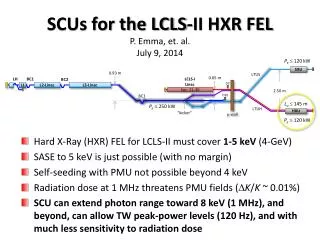
Post-Laser-Heater Diagnostics Line TCAVX spectrometer x-dogleg TCAVY OTR2 y-kicker 3 OTRs (120) x-septum hy = 540 mm Thanks M. Woodley & Y. Nosochkov
Floor Coordinates 21.5 cm clearance (center-to-center) 6
Resolution Requirements • Resolve rms beam sizes of order ~30 mm to < 5% • Deflectors should slice 1-mm bunch length into at least 10 bins (300 fs) • Must resolve ½ of 5-keV heater energy spread (i.e., 2.5×10⁻⁵) • Panofsky-Wenzel effect in TCAVX should be ¼ of 5-keV • Use short (< 1 m) S-band RF deflector(s) – X-band not needed here gex,y= 0.45 m sE = 5 keV sz= 1.0 mm E = 100 MeV Q = 100 pC
proj-gex slice-gey 37 m 37 m proj-gey sz 400 m 37 m SCREEN-1 (OTRB) SCREEN-1 (OTRB) 2 TCAV’s OFF TCAVXON (0.5 MV) TCAVX (sy 110 m) 377 m sz slice-gex TCAVY OTRB 37 m SCREEN-1 (OTRB) TCAVYON (0.5 MV) future
21 m sE sE 34 m syb 21 m 5.0 keV LH 1.0 keV PW 118 m 523 m SCREEN-2 (OTR2) SCREEN-2 (OTR2) TCAVXON (0.2 MV) HEATER OFF (sE =0) 2 TCAVs OFF spectr. TCAVX sE 34 m TCAVY 5.0 keV LH OTR2 523 m hy = 540 mm SCREEN-2 (OTR2) TCAVXON (0.2 MV) HEATER OFF (sE =5 keV) CSR causes no issues
269 m 269 m sE 1.0 keV PW 119 m 523 m SCREEN-2 (OTR2) SCREEN-2 (OTR2) TCAVXON (0.2 MV) HEATER OFF (sE =0) 2 TCAVs OFF 269 m 1.0 keV PW sx = 110 mm V = 0.2 MV f= 2856 MHz sE 5.0 keV LH 523 m TCAVXON SCREEN-2 (OTR2) TCAVXON (0.2 MV) HEATER OFF (sE =5 keV)
sdm (26 mm)/hy = 4.8×10⁻⁵ sdm (38 mm)/hy = 7.0×10⁻⁵ hy= 540 mm qy = 20 hy= 540 mm qy= 20 38 mm 26 mm sd= 1.0×10⁻⁵ (PW) sd= 5.0×10⁻⁵(LH) sdm (32 mm)/hy = 4.0×10⁻⁵ sdm (52 mm)/hy = 6.4×10⁻⁵ hy= 810 mm qy = 30 hy= 810 mm qy= 30 52 mm 32 mm sd= 1.0×10⁻⁵ (PW) sd= 5.0×10⁻⁵(LH) (eyby)1/2= 20 mm
Spectrometer at Low Charge (Q = 10 pC, gey = gex = 0.15 mm) sdm (16 mm)/hy = 2.0×10⁻⁵ sdm (45 mm)/hy = 5.6×10⁻⁵ hy= 810 mm qy = 30 hy= 810 mm qy= 30 45 mm 16 mm (eyby)1/2= 12 mm sd= 1.0×10⁻⁵ (PW) sd= 5.0×10⁻⁵(LH) sE sE
Chromatic Errors 0.05% rms energy spread (nominal) 0.20% rms energy spread (worst?)
No CSR Effects (100 pC, 1 mm bunch length) Linear energy-position correlations (dispersion) removed qy = 30 (0.05% rms energy spread) 6×10⁻⁵ 5×10⁻⁵
Chromatic Limitation on Dog-Leg Length L hy Quad focal length: Chromatic aberration: Dog-Leg length: Laser Heater: b = 20 m, sd = 0.2%, De/e0 1%, L ≥ 2.3 m BC1: b = 20 m, sd = 2.0%, De/e0 1%, L≥23 m