Download
1 / 19
190 likes | 346 Vues
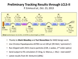
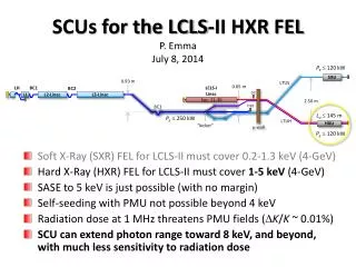
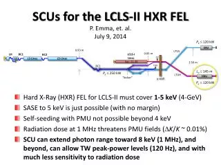
LCLS-II Bypass Line Design Goals P. Emma, July 7, 2010. Provide 14-GeV (?) electron bypass line from sector-20 around LCLS-I , feeding new undulators south of LCLS-I at 2 to 4-deg angle Use existing PEP-II 9-GeV line on linac ceiling (2’ above & 2’ south of linac)

E N D
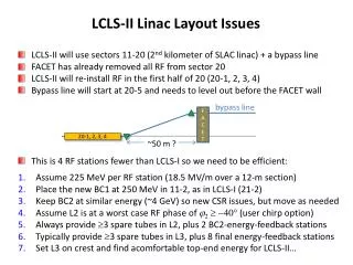
LCLS-II Bypass Line Design GoalsP. Emma, July 7, 2010 • Provide 14-GeV (?) electron bypass line from sector-20 around LCLS-I, feeding new undulators south of LCLS-I at 2 to 4-deg angle • Use existing PEP-II 9-GeV line on linac ceiling (2’ above & 2’ south of linac) • Sneak line around crowded BSY and BTHW • Bore new hole in 17-m thick iron m-plug wall • Preserve 0.6-mm emittance with up to 3 kA at 14 GeV • Include diagnostics and corrections in design
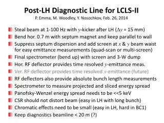
Bypass-Line Components • Extract beam out at 20-5 (use half of sec-20 RF) • Rolled x/y bends to existing 9-GeV PEP-II line • (Existing PEP-II extraction bends blow up LCLS emittance by factor of 4 – redesigned here) • Use 1-km of existing FODO cells (bmax = 400 m) • Also use long FODO as emittance diagnostic • Remove 4.6-mrad pitch of linac (as in LCLS-I) • Bend south with LCLS bend-cells (four 1-deg cells) • Keep beamline at bypass line height (25.5” up) • Bore new tunnel in hill 25.5” higher than LCLS-I • Add final wire scanner section & undulator matching (+ room for ECHO seeding)
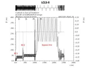
9-GeV 3-GeV 25.512” 17” 25.512” Inside Linac Vault - Looking Down-Beam 120” 47” LINAC 66” (ID-344-013-30) 132”
LCLS-II Bypass Layout N 17-m thick m-plug wall Dx = 25.5” PLAN VIEW 17-m thick m-plug wall Dy= 25.5” Sector 20-5 ELEVATION VIEW
24 30 26 28 23 25 27 29 existing quads on ceiling Sector-20 (20-5) m-plug wall
m-plug wall eight 0.5-deg bends
LCLS-I Head-HouseLayout (R. M. Boyce)
Linac Tunnel Approaching BSY LINAC Bypass Line will pass through most congested area in BSY SIT Line to PEP-II
With CSR (uniform temporal dist.) – note that ISR is no problem gex,y = 0.6 mm
Longitudinal phase space at 13.6 GeV, 3 kA, with CSR (uniform temporal dist.)
Questions • Is this 2-4-deg option the choice (2 other options exist, but all need a bypass line)? • Will we run at 7 GeV/360 Hz, or 14 GeV/120 Hz, or both (assuming both for now)? • Can a new hole be bored in the 17-m thick m-plug wall ? • Can we tunnel the new undulator hall 25.5” higher in elevation than LCLS-I ? • Do we need a jumper line from LCLS-I to LCLS-II, and the reverse? • Do we want a horizontal spreader to someday feed 2 undulators in the new hall ?