Download
1 / 20
200 likes | 496 Vues
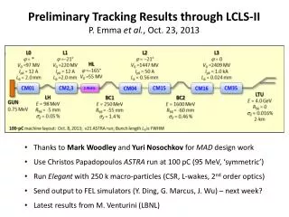
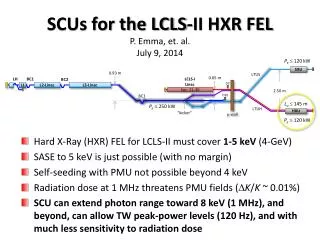
SCUs for the LCLS-II HXR FEL P. Emma, et. al. July 9, 2014. Hard X-Ray (HXR) FEL for LCLS-II must cover 1-5 keV (4-GeV) SASE to 5 keV is just possible (with no margin) Self-seeding with PMU not possible beyond 4 keV Radiation dose at 1 MHz threatens PMU fields ( D K / K ~ 0.01%)

E N D
SCUs for the LCLS-II HXR FELP. Emma, et. al.July 9, 2014 • Hard X-Ray (HXR) FEL for LCLS-II must cover 1-5 keV (4-GeV) • SASE to 5 keV is just possible (with no margin) • Self-seeding with PMU not possible beyond 4 keV • Radiation dose at 1 MHz threatens PMU fields (DK/K ~ 0.01%) • SCU can extend photon range toward 8 keV (1 MHz), and beyond, can allow TW peak-power levels (120 Hz), and with much less sensitivity to radiation dose Pe 120 kW SXU 0.93 m LTUS 0.65 m LCLS-I Linac LH BC1 BC2 D2 L1 L2-Linac L3-Linac 2.50 m Sec. 21-30 D10 BC3 Lu 145 m Pe 250 kW LTUH HXU “kicker” m-wall Pe 120 kW
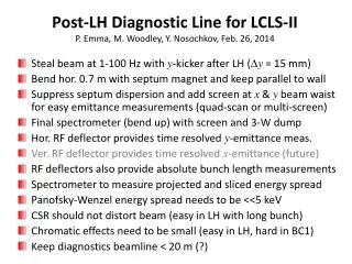
magnetic gap is 2.3 mm larger than vac. gap, g E = 4.0 GeV (nominal) PMU g = 5 mm NbTi Nb3Sn g = 4 mm g = 4 mm 4.8 keV SASE 7.6 keV SASE 145 m 6.8 keV SASE gex,y= 0.40 mm Ipk = 1 kA sE = 500 keV b = 16 m 20% Lu margin 3.4-m seg’s 1.0-m breaks 1 und. missing 1.5 keV low-lim. lu = 25.6 mm, 18.4mm, 16.8 mm K = 0.6-2.4, 1.1-3.0, 1.3-3.2 B = 0.2-1.0T, 0.6-1.8 T, 0.8-2.0 T
magnetic gap is 2.3 mm larger than vac. gap, g E = 4.2 GeV (stretch) PMU NbTi g = 5 mm Nb3Sn g = 4 mm g = 4 mm 145 m 8.2 keV SASE gex,y= 0.40 mm Ipk = 1 kA sE = 500 keV b = 16 m 20% Lu margin 3.4-m seg’s 1.0-m breaks 1 und. missing ~7 keV HXRSS limit lu = 25.6 mm, 18.4mm, 16.8 mm
magnetic gap is 2.3 mm larger than vac. gap, g E = 4.8 GeV (20% upgrade) PMU g = 5 mm NbTi g = 4 mm 10 keV SASE 145 m Nb3Sn g = 4 mm 8.3 keV HXRSS limit lu = 25.6 mm, 18.4mm, 16.8 mm
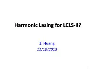
TeraWatt Peak Power Possible Add field taper to SCU 1.2 TW P (TW) Nb3Sn gm = 7.2 mm ge = 0.4 um E = 7.8 GeV f = 120 Hz Ipk = 4 kA z (m) C. Emma, C. Pellegrini, Z. Huang
Possible SCU Layout in LCLS-II (HXR) Joel Fuerst, ANL
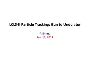
Joining Three 1.5-m Magnets into a Single 4.5-m Device • Magnets conduction cooled through gap separation extrusion • Gap separation ensures “seamless” core-to-core joint • Core center channels may be omitted
Joining Two 1.5-m Segments (13 cm extra) • Compact phase shifter uses one end corrector from each undulator and one extra dipole magnet in between • Distance between the undulator cores ~13 cm for this layout (could be reduced if alignment quadrupoles are not necessary) • Joint sections for Nb3Sn undulator are 4 cm long for each core Alignment verification quads and Bx correction Second Field Integral with phase shifter -2k Lb +k +k Lb Phase shifter dipole End corrector End corrector
Cold Break (quadrupole magnet) Conceptual design of a compact quadrupole magnet at breaks • Directly attached to undulator cold mass • Integrated quadrupole strength of 4 T (LCLS-II) can be obtained • Independently powered coils can be used for x-field correction Quadrupole Magnet End corrector
Vertical Alignment with Alignment Quadrupoles • Use reference quads at each end of ~3-m structure • Tuning and calibration based on line between magnetic center of two quads • Fiducialization performed with stretched wire measurement and referenced to fiducials on outside of cryostat • Allows for beam based alignment by moving cryostat to find center of quads with electron beam Small Alignment Quad Full Length Quadrupole
DC Resistive-Wall Wakefield (cold bore & warm) cold bore Cu Al warm bore Cu Al
SCU Advantages • Dramatically improved HXR-FEL performance (~7 keV with SC-Linac & 1-TW with Cu-Linac) • Orders of magnitude less radiation dose sensitivity (1 MW!) • No mechanical motion (DC power supply drives each segment) • Less tunnel space required – looks like LCLS-I und. (?) • Can easily be arranged as vertical polarizer (hor. fields) • Cryo-plant (4.5K, 280 W) might serve as injector stand-in at 2K (7.5M$) – cryo-dist. system not incl. • Might drop 5 linac CM’s (3.4 GeV) and still get 5 keV (Ti or Sn)? • Or drop 10 linac CM’s (2.8 GeV) and still get 4 keV (Sn only)?
Questions 1. What decision criterion should be used to make this technology decision in 2015. 2. What is the impact on the LCLS-II project schedule and what additional resources are needed to develop production SCUs and install them by the same April 2018 date presently planned for the PMUs? 3. What other subsystems would have to be developed / designed / specified and become part of the baseline? How would they fit into the facility / tunnel? 4. What other reviews would we have to organize before this could become baseline? 5. What other assurance would you want as the project director before you can support the change?