Download
1 / 15
150 likes | 349 Vues
Undulator Tolerances for LCLS-II using SCUs. Heinz-Dieter Nuhn (SLAC) Superconducting Undulator R&D Review Jan. 31, 2014. Outline. Tolerance Budget Method Tolerance Budget Energy Dependence of Performance Predictions Beam Heating Estimates Summary.

E N D
Undulator Tolerances for LCLS-II using SCUs Heinz-Dieter Nuhn (SLAC) Superconducting Undulator R&D Review Jan. 31, 2014
Outline • Tolerance Budget Method • Tolerance Budget • Energy Dependence of Performance Predictions • Beam Heating Estimates • Summary
Undulator Errors Affect FEL Performance FEL power dependence modeled by Gaussian. Sensitivities originally determined with GENESIS simulations developed with Sven Reiche. Several sensitivities have been verified experimentally with LCLS-I beam. Goal: Determine rms of each performance reduction (Parameter Sensitivity si) Effect of undulator segment strength error randomly distributed over all segments. FEL Power (Pi)
Analytical Approach* • For LCLS-I, parameter sensitivities were obtained by FEL simulations at max. energy, where tolerances are tightest. • LCLS-II has a 2-dimensional parameter space (photon energy vs. electron energy). • Finding the conditions where tolerance requirements are tightest requires many simulation runs. • To avoid this, an analytical approach to determine sensitivities, as functions of e-beam and FEL parameters, has been developed. • *H.-D. Nuhn et al., “LCLS-II UNDULATOR TOLERANCE ANALYSIS”, SLAC-PUB-15062
Undulator Parameter Sensitivity Calculation Example: Launch Angle • As seen in E-loss scan, dependence of FEL performance on launch angle can be described as Gaussian with rms sQ. • Comparing E-loss scans at different energies reveals the energy scaling. • This scaling relation agrees to what was theoretically predicted for the critical angle in an FEL: • * • When calculating coefficient B using the measured scaling, we get the relation • *T. Tanaka, H. Kitamura, and T. Shintake, Nucl. Instr. Methods Phys. Res., Sect. A 528, 172 (2004).
Undulator Parameter Sensitivity Calculation Example: Phase Error • In order to estimate sensitivity to phase errors, we note: the launch error tolerance (previous slide) corresponds to a fixed phase error per power gain length s • Path length increase due to sloped path. • Now, make assumption that sensitivity to phase errors over a gain length is constant. • For LCLS-I we obtain a phase error sensitivity of for each break between undulator segments based on GENESIS 1.3 FEL simulations. • In these simulations, the section length corresponds roughly to one power gain length. Therefore we write the sensitivity as • The same sensitivity should exist for all sources of phase errors.
Undulator Parameter Sensitivity Calculation Example: Undulator Vertical Misalignment • The undulator K parameter is increased when electrons travel above or below mid-plane: • Note the dependence on the inverse square of the undulator period. • This causes a relative K error of • Here, it is not the parameter itself that will be modeled by a Gaussian, but a function of that parameter. • Using the fact that the relative K errorcauses a Gaussian performance degradation we write • The sensitivity that goes into the tolerance budget analysis is • resulting in a tolerance for the square of the desired value, which can then easily be converted
LCLS-II HXR Tolerance Budget (SCU/Cu Linac) Ee = 15 GeV Ep = 25 keV lu = 2.0 cm, gmag = 7.5 mm, for Nb3Sn DK/Krms tolerance These tolerances are challenging, but quite similar to the successful LCLS-I tolerances.
Tolerances Effects are Energy Dependent Ee = 15 GeV Ep = 25 keV P/P0=67% FEL Power Reduction Proposed OperationalRange has Excellent Performance lu = 2.0 cm gmag = 7.5 mm Nb3Sn Photon Energy (keV) Electron Energy (GeV)
Performance Sensitivity to Main Tolerances lu = 2.00 cm Dy= ±60 mm Dfrms= ±5 deg DK/K= ±3.0×10⁻⁴ Same as on previous slide: Significant violation of tolerances does not cause catastrophic failure. lu = 2.00 cm Dy= ±120 mm lu = 2.00 cm Dfrms= ±23 deg lu = 2.00 cm DK/K= ±6.5×10⁻⁴
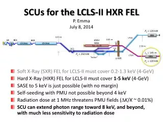
Chamber Heating • Only a fraction of this power will contribute to vacuum chamber heating. • There are two main beam related sources that can heat the LCLS-II vacuum chamber: (1) Resistive Wall Wakefields, (2) Spontaneous Radiation. • Beam Parameters: • Electron Energy: 4 GeV • Bunch Charge: 300 pC • Bunch Repetition Rate: 100 KHz • => Average Electron Beam Power: 120 kW • (1) Total Spontaneous Radiation Produced (ignoring microbunching) • SC-HXU Undulator gap: 7.5 mm • SC-HXU Undulator Period: 1.85 cm • SC-HXU K: 3.31 • <dP/dz> = 1.1 W/m. • (2) Resistive Wall Wakefields • Beam Pipe Radius: 2.5 mm • Beam Pipe Profile: parallel plates • Ipk= 1000 A • Chamber Material: Al • Conductivity: 37.7×10⁶W-1m-1 • <dP/dz> = 0.26 W/m
Summary • A tolerance budget method was developed for the LCLS-I undulator (PMU) • Those sensitivities have since been verified with beam based measurements • The method is being used for LCLS-II SCU undulator error tolerance budget • The SCU tolerances are challenging, but similar to LCLS-I • Radiation based vacuum chamber heating appears modest.