LCLS-II Transverse Tolerances
180 likes | 382 Vues
LCLS-II Transverse Tolerances. Tor Raubenheimer May 29, 2013. LCLS-II Accelerator Parameters. Tolerance Specifications. Transverse tolerances to minimize emittance dilution, optical errors and beam jitter

LCLS-II Transverse Tolerances
E N D
Presentation Transcript
LCLS-II Transverse Tolerances Tor Raubenheimer May 29, 2013
Tolerance Specifications • Transverse tolerances to minimize emittance dilution, optical errors and beam jitter • Tolerances based on most stringent conditions – usually 10 pC with 0.17 mm-mrad emittance and over-compression with 0.5% DE/E • Sources include alignment errors, magnet harmonics, PS fluctuations, component vibration, and coupling from other sources • Jitter tolerances set to limit beam motion to 33% rms in undulator from all sources • All tolerance specifications are rms values • Full tuning / bump studies not completed
Transverse Jitter Sources • Based on ge = 0.15 mm-mrad, N = 250 pC, sE/E = 0.5% and D/s<33% (DI/I = 15%)
Comparison with LCLS-I Tolerances • LCLS-I quad jitter tolerances were specified to limit the beam expected amplitude to 10% of the rms beam size. • The amplitude is sqrt(2) larger than the rms offset • LCLS-II tol. are specified for 33% rms jitter from all sources • Although not specified, it looks like LCLS-I tolerances were specified for 1 mm-mrad versus 0.17 mm-mrad for LCLS-II LCLS-II total jitter budget is ~2x looser • Quadrupoles are small fraction of jitter budget quadrupole jitter requirements are 1.7x tighter
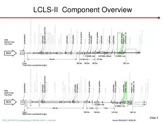
Current and Energy Jitter Transverse • Beam current jitter couples to transverse jitter through transverse wakefields and CSR • Beam energy jitter couples to the transverse jitter through residual dispersion, coupling to wakefields in dispersive regions and changes in phase advance CSR Cancellation Septum kick for 250 pC, 3 kA Longitudinal Wakes for 250 pC, 3 kA
Steering Correctors • Largest potential source of beam jitter at ~20% DX,Y/sX,Y • MCOR power supplies limited to ~1e-4 DI/I • LCLS-I specified 3e-5 toelrances for many dipole correctors • Sizes of MCORs reduced to balance corrector strength to reasonable values ease tolerances • Used ‘reasonable’ maximum quadrupole alignment errors and compared to typical LCLS-I corrector strengths
Steering Correctors (2) L1 / L2 values are < 10 G-mL3 values < 20 G-m BC2 values large
Steering Correctors (3) • Maximum quadrupole misalignments for corrector sizing
Steering Correctors (4) • Most correctors could correct a local large misalignment • In some cases, multiple (2) correctors will be required
Steering Correctors (5) • Not showing Tables – look in PRD! • Most correctorsmuch weaker thanin LCLS-I specsbut similar to LCLS-I operatingvalues • L1 / L2 / L3 correctors are all much weaker thanSLAC linac • LTU sized at 60 G-m and dump correctors are 120 G-m
Dipole Magnets (1) • Achromatic magnet strings should be largely insensitive to power supply fluctuations • In practice, magnets are only matched at 1% level and include +/- 1% trims to match magnets • Power supply regulation tolerances calculated to limit (1) change in path length, (2) transverse trajectory in achromat, and (3) transverse jitter due to 1% magnet mismatch • Dipole string PS are medium PS with 5e-5 regulation • Trim power supplies are standard MCORs with 2e-4 regulation
Dipole Magnets (2) • Roll jitter tolerances vary between 1 and 10 urad • Dipole roll jitter is 2nd largest DY/sY jitter source • Roll alignment tolerance is set to limit dispersion errors and trajectory • Dipole roll alignment tolerances vary between 0.3 and 5 mrad • These may be overly tight and can iterate as needed
Quadrupole Magnets (1) • Quadrupole vibration tolerances are the 3rd most important source of beam motion • Typical values vary between 100 and 50 nm • Quadrupole alignment set loosely by increase in projected beam sizes • Typical values rangebewteen 300 and 100 um • Without bumpsDe/e ~ 500%
Quadrupole Magnets (2) • Quadrupole vibration tolerances tight in BC1, BC2, Bypass extraction and LTU – typical jitter contributions <1% magnet • May want to work on S20 quadrupole supports Vibration Tolerance [um] LTU BC1 BC2 S20 and Bypass extraction
Quadrupole Magnets (3) • Quadrupole power supply regulation tolerances are calculated to minimize (1) Db/b, (2) Dh*sE/E, and (3) jitter due to trajectory errors: 3e-5 DI/I minimum tolerance • For jitter calculation assumed quadrupole center-to-trajectory of 100 um in BC2, Bypass ext. & Undulator; 200 um in BC1 & LTU; 1000 um in Bypass; 300 um elsewhere LTU Arc Bypass extraction
Transverse TolerancesAlignment Tolerances • Alignment numbers provide guidance beam-based tuning • Slice e impact is small(slice = 1% of sZ) • Projected e impact is large • Calculated for over-compressed case with 0.5% DE/E • Alignment: 300 um on rf structures and most quadrupoles; 200 um in BC1 and LTU; 100 um in BC2, Bypass and Undulator • X-band structure transverse wake is 40x larger than S-band yielding 30% projected De/e growth by itself (slice De/e are ~2%)
Magnet Field Tolerances • Detailed magnet tables for all dipoles, quadrupoles and steering correctors • Multipole tolerances calculated using 250 pC (0.5 mm-mrad) over-compressed beam (0.5% DE/E) plus steering errors of 0.5 mm except 1 mm in injector, bypass and undulator • Multipole tolerances are relatively loose except where there is dispersion • Uncorrelated effect on beam core is small <5% De/e and<0.1% DK/K Partial table for SXR LTU quads