Download
1 / 19
190 likes | 294 Vues
Hard X-ray S-2-E FEL simulation for LCLS-II CDR. J. Wu In discussion with Y. Ding, P. Emma, Z. H uang, H.-D. Nuhn 02/01/2011. LCLS-II: Ranges for Individual Bunch Operation. Simulation example. (From H-D Nuhn, 10/13/2010). Setup. FEL at 13.5 keV ,

E N D
Hard X-ray S-2-E FEL simulation for LCLS-II CDR J. Wu In discussion with Y. Ding, P. Emma, Z. Huang, H.-D. Nuhn 02/01/2011
LCLS-II: Ranges for Individual Bunch Operation Simulation example (From H-D Nuhn, 10/13/2010)
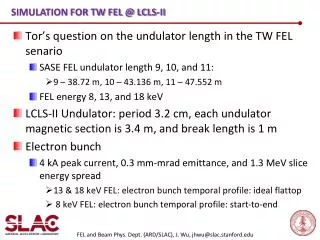
Setup • FEL at 13.5 keV, • Electron Centroid Energy 13.5 GeV; peak current 3 kA • S2E file down to undulator entrance taken from P. Emma • Undulator lw = 3.2 cm; each section is about 4.4 m long with 3.4 m magnetic length; beta-function ~ 20 m
Electron bunch @ undulator entrance • Current profile (head at right)
Without wakefield • The S2E input electron distribution function is injected into an ideal undulatorwithout any wakefield effect
FEL power • Along the undulator: Saturation around 60 m
FEL profile and spectrum • Along the undulator at 100 m
Energy loss • Along the undulator: entrance (black), 60 m (red), 120 m (blue), and 150 m (green) – electron bunch head at right
Energy spread • Along the undulator: entrance (black), 60 m (red), 120 m (blue), and 150 m (green) – electron bunch head at right
Setup • FEL at 13.5 keV, • Electron Centroid Energy 13.5 GeV; peak current 3 kA • S2E file down to undulator entrance taken from P. Emma (No LSC included) • Undulator lw = 3.2 cm; each section is about 4.4 m long with 3.4 m magnetic length; beta-function ~ 35 m
With resistive-wall wakefield • We assume 5 mm diameter round aluminum pipe; no surface roughness wake, no geometric wake; head at left
FEL power • Along the undulator: Saturation around 80 m; with wakefield compensation of 150 keV/m which in reality is a tapering in the undulator
FEL power • Along the undulator: 80 m – electron bunch head at left
FEL power • Along the undulator: 100 m – electron bunch head at left
FEL power • Along the undulator: 120 m – electron bunch head at left
FEL power • Along the undulator: 140 m – electron bunch head at left
FEL spectrum • At the undulator end: 140 m– electron bunch head at left
FEL spectrum • The wide spectrum is partially due to the wakefield induced energy chirp along the electron bunch, head at left