Download
1 / 37
370 likes | 488 Vues
This document outlines the diagnostic strategies for the LCLS project from January 19-20, 2004, including assumptions regarding undulator placement and alignment, motion control, and temperature compensation. It discusses key elements such as X-ray diagnostics, electron beam parameters, and the use of NdFeB magnets, while addressing radiation damage issues and the implementation of phase error corrections. Insights into undulator design, maintenance plans, and the introduction of additional undulators are also provided, forming a comprehensive overview of diagnostic systems for synchrotron applications.

E N D
X-Ray Diagnostics for the LCLS Jan. 19-20, 2004 UCLA
General Assumptions (See CDR) • Undulators Fixed in Position • Exception: Small motion for alignment • Fixed Gap Undulators • Permanent Magnet Quads • Cavity BPMs following each undulator and prior to the 1st • Full suite of diagnostics every third undulator
Current Thinking • Use NdFeB • Radiation Damage Issue • Real benefit of Sm2Co17 still no known • Must determine acceptable losses • APS is doing this for operational reasons • 7 Additional undulators planned for use in regular maintenance schedule • Temperature Compensation • Sm2Co17 slightly more than a factor of 2 better. Not enough.
Current Thinking • K Adjustment/Control Strategy a All calculations were made according to a tolerance of 1.5x10⁻⁴ and a total range of 1.5x10⁻³ (20 Gauss) for DBeff/Beff. Spacer thickness steps were chosen to allow full compensation at half travel of the total range of motion. b The range of horizontal motion listed in the parentheses corresponds to ±1°C temperature compensation. To allow for temperature compensation of ±1°C the additional range of motion listed in parentheses should be provided.
Undulator segment tolerances a Total allowed phase slippage including all errors. The error in the effective magnetic field Beff, totally dominates the contributions.
Calculated gain length and increase in saturation length using a random uniform distribution of K values from one undulator to the next with end-phase corrections applied for the LCLS beam parameters.a a Normalized beam emittance was 1.5 mm-mrad, beam energy spread 2.1x10⁻⁴, FODO lattice strength 0.112 m-1, and peak current 3.5 kA. Other parameters same as in Table 1. b The gain length was derived over the next-to-last super period of six undulators. c The increase in saturation length was estimated near 100 m by determining how much additional distance was needed to reach the same level of ln|J|2. * Same value as for DK/K = 0.
Current Thinking • Undulator System Fully Installed on day 1 • Start at 800 eV • Why?
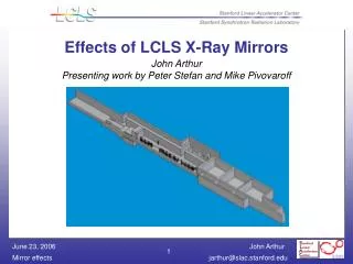
Cell structure of the LCLS Undulator Line 852 627 3420 UNDULATOR 11528 mm Horizontal Steering Coil 33 Undulators ~ 130-m Overall Length Vertical Steering Coil Beam Position Monitor X-Ray Diagnostics Quadrupoles Office of Science U.S. Department of Energy Pioneering Science andTechnology
PRIOR WORK FOR INTRA-UNDULATOR DIAGNOSTICS (CDR April 2002) Electron Beam Diagnostics (Section 8.11, Glenn Decker and Alex Lumpkin) Table 8.9 Undulator electron beam diagnostics * Non-intercepting X-ray Diagnostics (Section 8.13, Efim Gluskin and Petre Ilinski) • On-axis diagnostics • Diamond (111), 4 – 9 keV, cooled silicon PIN diode. • Off-axis diagnostics • Hole crystal, 2q = 90, CCD detector.
Issues • Quad Fixed to the Undulator • Has implications on using the cant for tuning • Requires separate motion • Tunnel Temperature Control • Would like better than +/- 0.2 Degrees C. • Supports will probably need this or better • 800 eV • Makes life very difficult for the x-ray diagnostics • Would prefer to start a > 2 KeV
Issues • Motion Capability • We need some for K tuning but… • Do we need the ability to completely remove the undulators? • Aside: 0.1 G deflects the 14 GeV beam by ~1.5 um in 3.7 m. • High Power Damage • Can we even make a diagnostic that is both useful and can handle the power densities of the FEL?
Issues • Radiation Damage • We will use NdFeB • We must protect the undulator from radiation • This has implications on intraundulator interceptive diagnostics • Canted Poles • BBA • There will be some arbitrary offset and anle through the undulator • How does this impact the K tuning?