Download
1 / 41
410 likes | 574 Vues
Optimizing X-ray FEL performance for LCLS at SLAC. Sean Kalsi on behalf of SLAC MCC operations group, WAO August 8, 2012 . Outline. Free Electron Lasers LCLS Overview Deliverable X-Ray Parameters Setting Up the Machine Tuning Methods FEL Performance References

E N D
Optimizing X-ray FEL performance for LCLS at SLAC Sean Kalsi on behalf of SLAC MCC operations group, WAO August 8, 2012
Outline • Free Electron Lasers • LCLS Overview • Deliverable X-Ray Parameters • Setting Up the Machine • Tuning Methods • FEL Performance • References • Supplemental Information LCLS FEL WOA 2012
Introduction to Free Electron Lasers FEL uses a bunch of unbound electrons • Amplification of stimulated emission due to a resonance condition • Resonance condition setup with Electron/Radiation interaction in array of undulator magnets Why use FEL? • High Power (GW) • Coherent Beam • Short pulses(fs) • High spatial and temporal resolution of Atomic and Molecular Processes LCLS FEL WOA 2012
Introduction to Free Electron Lasers • Start with electron bunch entering periodic undulator array • Electron will emit radiation spontaneously as it traverses the undulator LCLS FEL WOA 2012
Introduction to Free Electron Lasers • Once enough X-Rays produced the co-propagating photon bunch will micro-bunch the electron beam • Micro-Bunched electron beam will then emit radiation coherently to amplify and produce the FEL • This process of generating an FEL is called Self Amplification by Stimulated Emission(SASE) LCLS FEL WOA 2012
Introduction to Free Electron Lasers • Poor Temporal Coherence(only coherent in each spike): • Hundreds of ~fs spikes make • up FEL pulse due to SASE • Intensity builds up along • length of Undulator • Good Transverse Coherence: • Coherence builds up along • length of the Undulator LCLS FEL WOA 2012
Introduction to LCLS: Electron Transport • 120Hz Pulsed Bunches using 2856MHz RF • RF Gun(6MeV), UV Drive Laser, Photo-Electric Emission • Cu Cathode, 20-350pC, 300-600µm Bunch • Laser Heater(controlling slice energy spread) • 1st Bunch Compressor(factor of ~10) BC1 • 2nd Bunch Compressor BC2 • Compress down to 0.5-10+µm(2fs-300fs) gun 4 wire scanners + 8 coll’s 4 wire scanners + 6 coll’s L1X L0 TCAV0 3 wires 2 OTR 3 OTR vert. dump L1S stopper heater m wall sz1 sz2 3 wires 3 OTR L2-linac DL1 135 MeV BC1 220 MeV BC2 5 GeV TCAV3 BSY 3-15 GeV DL2 undulator L3-linac stopper LCLS FEL WOA 2012
Introduction to LCLS: Photon Transport 6 AMO SXR XPP XCS CXI MEC Front End Enclosure(FEE): Gas Detectors, Slits, Attenuators, K-Mono, Direct Imager Near Experimental Hall Hutches: AMO & SXR (Soft X-Rays) XPP (Hard X-Rays) Far Experimental Hall Hutches: XCS, CXI & MEC (Hard X-Rays) 6 Total Experiment Sites LCLS FEL WOA 2012
LCLS User Parameter Space • Photon Energy • 480eV to 10.6keV • Photon Pulse Length • 2 to 300+ fs • Energy Bandwidth • 0.2% (narrow) or 2%(wide) • Normally 2+ Configuration Changes Per 24/hours. For now 1 user at a time, switch every 12 hours LCLS FEL WOA 2012
Setting up the Machine • Keys to FEL Performance • Lowest Electron Transverse Emittance • Optimal Electron Bunch Length • Slice Energy Spread Sufficient to Generate SASE • Optimal Undulator Configuration LCLS FEL WOA 2012
Setting up the Injector • Starting point for good emittance is quality of beam off the cathode • UVDriveLaser Transverse and Temporal Quality • Scan Cathode to find optimal QE and Emittance spot LCLS FEL WOA 2012
Setting up the Injector • Use injector optics to tune for best transverse emittance • OTR Screens and Wire Scanners for beam size measurements • Can also examine slice emittance in X plane • Clue about temporal quality of laser LCLS FEL WOA 2012
Setting up the Linac • Goal: Preserve Injector Emittance • Emittance Measurement Points(wires): After 1st and 2nd bunch compressor , then upstream of Undulator • Steer to Flat Orbit in Linac and Linac to Undulator Region • Beta and Dispersion Match LCLS FEL WOA 2012
Setting up the Undulator • Goal: Keep the Electrons aligned with the X-Rays • Beam Based Alignment at 4 energies to find flattest trajectory • Uses all 33 Undulator BPM’s and Undulator Quads • Offsets in RF BPM’s drift due to electronics issues LCLS FEL WOA 2012
Setting up the Undulator Undulator Translation Stage: Moves Horizontally to vary magnetic field value in each segment(use for Taper) Pole Faces are tilted slightly Field varies(K value) Horizontally in position along pole face Beam Entrance LCLS FEL WOA 2012
Setting up the Undulator Undulator Taper: Needed to match Undulator Field to electron bunch that is losing Energy to FEL creation Quadratic taper in post saturation regime Helps maintain resonance condition after saturation Linear Taper in Exponential Gain Section LCLS FEL WOA 2012
Measuring the FEL Intensity • Start by measuring Energy Loss of Electron Bunch across Undulator • Suppress FEL by kicking with first corrector in the Undulator • Then Calibrate the Gas Detectors measuring the FEL pulse • FEL interacts with GAS emitting photons picked up by PMT’s(minimally invasive) • Use FEE Gas Detector display for real time Pulse Energy Information, and Tuning LCLS FEL WOA 2012
Tuning Methods • Capability for Minimally Invasive Tuning • Many experiments can handle tuning while beam is delivered • Most gains are made in FEL pulse energy in this mode LCLS FEL WOA 2012
Tuning Methods • Often Design Quad settings do not produce Best FEL • Start by setting up to design lattice, but sometimes we can double the FEL by • going off design • Use Beta and Dispersion Matching Quads to tune Drawback: Reproducibility • Laser Profile Steering • Start with uniform transverse profile, altering the profile will change bunch profile off of the Cathode • Undulator Taper Tweaks • The better you can match the energy loss profile the more FEL you can produce • Has a dependence on charge, energy, and bunch length LCLS FEL WOA 2012
Tuning Methods • Pulse Length in BC1 and BC2 • Can optimize directly on FEL Pulse Energy Difficulties: More Compression leads to more Energy Spread, which leads to more Jitter Pulse lengths of ~10 fs require lower charge which means less FEL power • Closed Bumps in Early Linac Orbit • Possible transverse wake field effects in the early part of Linac • Can use feedback setpoints or closed orbit bumps to compensate LCLS FEL WOA 2012
FEL Pulse Energy vs. FEL Photon Energy Note: Gaps around 3 and 5.5keV are due to lack of statistics LCLS FEL WOA 2012
Sources of Information and Figures • LCLS Physics: • A. Brachmann, W. Colocho, F. J. Decker, D. Dowell, P. Emma, J. Frisch, Z. Huang, R. Iverson, • H. Loos, H.D. Nuhn, J. Turner, J. Welch, J. Wu, F. Zhou • LCLS Control System and Diagnostic GUI’s • D. Fairley, J. Frisch, N. Lipkowitz, H. Loos, L. Piccoli, M. Zelazny • MCC Operations Group: • S. Alverson, L. Alsberg, T. Birnbaum, C. Blanchette, A. Egger, M. Gibbs, R. Gold, A. Hammond, C. Hollosi, S. Kalsi, C. Melton, L. Otts, B. Ripman, B. Sampson, D. Sanzone, A. Saunders, P. Schuh, H. Smith, T. Sommer, M. Stanek, E. Tse, J. Warren LCLS FEL WOA 2012
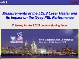
References 1.) LCLS Undulator PRD 1.4-001-r4, H. D. Nuhn et al. 5/2008 2.) Tapered Undulators for SASE FEL’s, W. Fawley, Z. Huang et al. 9/2001 3.) Measurements of the LCLS laser heater and its impact on the x-ray FEL performance, Z. Huang et al. SLAC-PUB-13854, 2009 4.) X-Band RF Harmonic Compensation for Linear Bunch Compression in the LCLS, P. Emma, 11/2001 5.) Link for LCLS Area Physics Requirement Documents: http://www-ssrl.slac.stanford.edu/lcls/internals/documents/prd/ 6.) A Review of X-ray Free-Electron Laser Theory, Z Huang, K. Kim, ANL-AAI-PUB-2007-002,December 2006 7.) FEL SPECTRAL MEASUREMENTS AT LCLS, J. Welch et al. Proceedings of FEL2011, Shanghai, China LCLS FEL WOA 2012
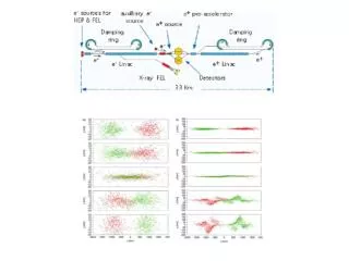
Bunch Compression at SLAC SettingChirp(to create compression in a Chicane) The head of the bunch needs lower energy than the tail. So RF phase is shifted negative. This will cause the head to take a longer path(effectively slow down), and the tail to take a shorter path(effectively speed up) through the chicane, leading to longitudinal compression. Horizontal is RF Pulse Vertical is Z position in DLWG Fig 1: Beam in center of DLWG; RF phase = 0 Deg. Fig 2: Beam in center of DLWG; RF phase = -20Deg. Fig 3: Beam in center of DLWG; RF phase = +20 Deg. Blue line represents arrival of Bunch in center DLWG. Pulse approximates RF distribution in cavity at bunch arrival time. Note: Beam arrival time in the DLWG does not change(always on blue line when RF is pulsed). The RF phase can shift to align the beam on various parts of the RF pulse. LCLS FEL WOA 2012
X-Band Chirp at SLAC • S-Band DLWG RF at 2.856GHz • Use X-Band(11.424GHz) for more uniform Chirp X-Band OFF: After BC1 X-Band ON: After BC1 LCLS FEL WOA 2012
Bunch Length Optimization • Choosing Bunch Length • Optimize on FEL Pulse Energy, Stability or Bandwidth Blue: Bunch Length( A) Green: FEL Pulse Energy(arb) X-Axis: Klystron Chirp FEL Goes to Zero at Max Compression LCLS FEL WOA 2012
Injector Laser Heater • Use IR Laser “Heater” to blow up and randomize initial slice energy spread • Optimize to eliminate Micro-Bunching induced from Bend Magnets in Compressors which will suppress SASE effect • Setup: Use Transverse Cavity to streak Beam in Y Plane, then send beam in X-Dispersive region to observe uniform slice energy spread increase LCLS FEL WOA 2012
Introduction to LCLS: Undulator Transport • Undulator Hall(100M) • 33 total Segments, each containing fixed magnets • 6.8mm Vertical Gap, Bend in Horizontal Plane • ~100 3cm periods per segment 4 wire scanners + 6 coll’s vert. electron beamdump stopper m wall BSY 3-15 GeV LTU undulator LCLS FEL WOA 2012
Soft X-Ray Operation • Soft X-Rays for LCLS < 2keV • Emittance Requirements less demanding • Optimal FEL at Longer Pulse Lengths • Shorter Gain Length • Laser Heater has stronger effect • Energy Jitter in Linac is a problem at shorter pulse lengths LCLS FEL WOA 2012
Feedback Displays Longitudinal Feedbacks Matlab Based, ~5Hz Energy Setpoints Pulse Length Control Transverse Feedbacks EPICS Based, up to 120Hz Ex: Injector Launch, Launch into Undulator LCLS FEL WOA 2012
Feedback Locations GUN TFB L1X TFB TFB vert. dump LFB LFB LFB TFB TFB L1S m wall LFB L2-linac TFB DL1 135 MeV BC1 220 MeV BC2 5 GeV BSY DL2 undulator L3-linac TFB TFB TFB TFB - Transverse Feedback in region LFB – Longitudinal Feedback in region LCLS FEL WOA 2012
Free Electron Lasers • Setting up resonance condition Undulator • As electron travels 1 period in the undulator, it slips behind a distance equal to one wavelength of the resonant X-Ray emitted Electron(black dot) co-propagating with seed pulse LCLS FEL WOA 2012
FEL Spot Size in FEE 8.4keV FEL Spot Size LCLS FEL WOA 2012