Download
1 / 15
150 likes | 167 Vues
This detailed report outlines the design and status of the Linac at LCLS, including parameters, operation plans, trajectory control, and commissioning progress. The document covers key aspects such as low-charge operation, project documentation, and trajectory jitter tolerances. The Linac system is set to undergo commissioning in January 2007 and 2008. Detailed plans for injector-BC1 commissioning and trajectory stability are discussed. The report also includes information on the accelerator and compressor schematic, peak current jitter reduction, and X-ray pulse improvement. Various project documentation and commissioning plans are outlined, highlighting the system's readiness for construction and commissioning phases.

E N D
Linac Design and StatusP. EmmaLCLS DOE ReviewSC1/SC2 BreakoutFebruary 8, 2006 LCLS
Outline • Linac intro. & parameters • Low-charge operation • Project documentation • Commissioning plans • Inj-BC1 commissioning • Trajectory jitter & tolerances • Summary
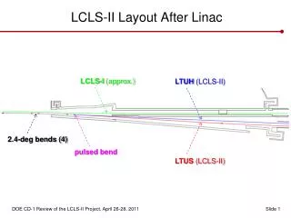
Commission in Jan. 2008 Commission in Jan. 2007 LCLS Accelerator and Compressor Schematic 250 MeV z 0.19 mm 1.6 % 4.30 GeV z 0.022 mm 0.71 % 13.6 GeV z 0.022 mm 0.01 % 6 MeV z 0.83 mm 0.05 % 135 MeV z 0.83 mm 0.10 % Linac-X L =0.6 m rf= -160 Linac-0 L =6 m rf gun L0-a,b Linac-3 L 550 m rf 0° Linac-1 L 9 m rf -25° Linac-2 L 330 m rf -41° 25-1a 30-8c 21-3b 24-6d ...existing linac 21-1 b,c,d undulator L =130 m X BC1 L 6 m R56 -39 mm BC2 L 22 m R56 -25 mm DL1 L 12 m R56 0 DL2 L =275 m R56 0 SLAC linac tunnel research yard
Low-Charge Option (200 pC) Charge: 1 nC0.2 nC Slice emittance: 1 mm0.8 mm Gun Current: 10030 A (10 ps6.5 ps) Final current:3.4 kA2.0 kA(same Lsat) und. wakes • BC2 CSR De 1/5 • L2 trans. wake De1/16 • Peak current jitter 1/2 • X-ray pulse 85 fs (was 200 fs) • ‘No’ undulatorwakes • PFEL 10 GW, 1012 photons • eng. baseline unchanged • 1-nC still fully supported • Full Elegant and Ginger/Genesis S2E’s completed 1 nC 0.2 nC
Project Documentation • Physics Requirements Documents (PRD) • Engineering Requirements Documents (ESD) 31 PRD’s & ESD’s 104 magnet sheets http://www-ssrl.slac.stanford.edu/lcls/internals/documents/prd/ http://www-ssrl.slac.stanford.edu/lcls/linac/specs/
Example PRD’s 1.1-006, Magnets 1.1-008, Vibrations 1.1-010, Polarities 1.3-017, Collimators
Machine Commissioning Plans • Work in MS-Project • One file/manager per system • Link to milestones and events in Master file Injector-BC1 BC2 LTU-und. install install Dec. ‘05 Sep. ‘07 Dec. ‘07 Mar. ‘08 Dec. ‘06 Aug. ‘06
Injector Through BC1 Commissioning no laser-heater sE gex,y and slice RF deflector E
Injector Through BC1 Commissioning (2) CSR relative bunch length monitor? BC1 sE stopper X-band RF gex,y E slice gey
Trajectory Stability – Sources of Jitter(f > 10 Hz; Use feedback for f < 10 Hz) • Steering coil current regulation (121 x, 121 y) • Bend magnet trim coil current reg. (13 x, 2 y) • Misaligned quads/sol’s + current reg. (148 mag’s) • Quad/solenoid mech. vibration (148 mag’s) • CSR kicks with bunch length jitter (BC2, x only) • Transverse wakes and charge jitter (X-band RF) • Drive laser pointing stability Expected Sources of Transverse Jitter
Quadrupole Magnet Vibration Existing Linac ‘QE’ Quadrupole Magnets R. Stege, J. Turner, 1994 rubber boot on water pump • 12 quads need rms 500 nm (most new injector quads) • 101 magnets need rms 100 nm (existing linac quads) • 35 quads need rms 50 nm (mostly new LTU quads)
CSR-Induced x-Trajectory Jitter 10% bunch length jitter 16% ‘core’ trajectory jitter 1-nC 22 mm 20 mm 18 mm core
Trajectory Stability – Tol’s & Expectations System Stability Requirements at f > 10 Hz • Steering coils (30-100 ppM 6% of beam size) • Trim coils (30-100 ppM 2%) • Misaligned quads (Dx 200 mm: 25-100 ppM 6%) • Quad/solenoid vibration (0.05-1 mm required 10%) • CSR kicks (1 nC, Dsz/sz 10%: ~20%, x-only) • Wakes (Dx 200 mm, DN/N 2% 2%) • Drive laser pointing ( 3%) 0.2 nC is more stable
Summary • Linac parameters are well defined and stable • Project documents describe requirements • Detailed commissioning plans exist and are being further advanced • Studies finished on collimation, machine tune-up, and expected trajectory stability • Longitudinal feedback needed (see J. Wu) • Linac through BC1 is ready for construction in Fall ’06 and commissioning in Dec. ’06.