Download
1 / 24
240 likes | 396 Vues
Linac Coherent Light Source (LCLS) Low Level RF Status. Safety First and Second and Third…..to Infinity. Hazards in the LLRF system RF 1kW at 120Hz at 5uS = 0.6 Watts average, 2 Watt average amps at 2856MHz, 60W average amps at 476MHz Hazards – RF Burns / Cataracts

E N D
Safety First and Second and Third…..to Infinity • Hazards in the LLRF system • RF 1kW at 120Hz at 5uS = 0.6 Watts average, • 2 Watt average amps at 2856MHz, • 60W average amps at 476MHz • Hazards – RF Burns / Cataracts • Mitigation – Avoid contact with center conductor of energized connectors. All employees working with LLRF systems are required to have the proper training. • 110VAC Connector • Hazards - Shock • Mitigation - Don’t touch conductors when plugging into outlet. • All chassis are inspected by UL trained inspector.
Status of Hardware for Injector Turn-on • Linac Sector 0 RF Upgrade • All 3 RF Chassis completed and Installed (Master Oscillator, Master Amp, PEP phase Shifter • Control Module ready for test – higher phase noise levels if not installed • Sector 20 RF distribution system • Phase and Amplitude Controllers (PAC) – 5 units • Phase and Amplitude Detectors (PAD) – 2 units • Phased Locked Oscillator – Use SPPS unit for Turn On • LO Generator – Complete - 75% tested – looks good so far • Multiplier – 476MHz to 2856MHz – Complete • 4 distribution chassis – Complete 102MHz, 2056MHz, 2830.5MHz • Laser Phase Lock – Needs testing – Only high risk item • Distribution Amplifiers – 10W, 2850MHz due Oct 25, 102MHz Amp being built • LLRF Control and Monitor System • 1 kW Solid State S-Band Amplifiers – 5 units – Design Complete, In Fab • PAD – 12 units – 6 required for turn on • PAC – 6 units • Bunch Length Monitor Interface – Will use PAD to collect data • Beam Phase Cavity • Will use 2 channels of PAD Chassis • Pill box cavity with 2 probes and 4 tuners – 2805MHz 3 units Complete
Status of Software for Injector Turn-on • PAD Software • Operational • PAC Software • Operational • Local Feedback (in VME) • Data analysis shows simple feedback algorithm will work. • Optimization of algorithm continues. • Time measurement: measure time needed for data acq, for transfer to VME, for VME processing, for transfer to PAC. • Time measurement: needed for multiple local loops. Eg. Measure scalability from 1 to N instances. • RF Gun Temperature Feedback • In Design • Calibration and Test • Operational • High Level Applications • In progress (This means we are working on specifications.) • Storing of boot params, serial numbers, etc in flash or on the board for PAD and PAC
Status of Documentation + Reviews • LLRF Control Design Specification • This Engineering Specification Document was signed off by Project Office on 9/27/2006. • LLRF Final Design Review • This review was held on 9/19/2006. • The scope of the review covered: • RF Distribution Reference System for Injector Commissioning • RF System for Injector Commissioning • PAD • PAC • VME • The goals of the review were: • Injector turn on is January 3, 2007. The designs of the prototype PADs and PACs have been built and tested. Fabrication is scheduled for October, 2006. Please review analysis of test data and the proposed design and comment on the proposed systems' ability to meet LCLS specifications. • Review our test plans and suggest improvements
LCLS Layout P. Emma
0.50 X- X-band LCLS RF Jitter Tolerance Budget Lowest Noise Floor Requirement 0.5deg X-Band = 125fS Structure Fill time = 100nS Noise floor = -111dBc/Hz @ 11GHz 10MHz BW -134dBc/Hz @ 476MHz RMS tolerance budget for <12% rms peak-current jitter or <0.1% rms final e− energy jitter. All tolerances are rms levels and the voltage and phase tolerances per klystron for L2 and L3 are Nk larger, assuming uncorrelated errors, where Nk is the number of klystrons per linac. P. Emma
Slow Drift Tolerance Limits (Top 4 rows for De/e < 5%, bottom 4 limited by feedback dynamic range) P. Emma, J, Wu (Tolerances are peak values, not rms) * for synchronization, this tolerance might be set to 1 ps (without arrival-time measurement)
Linac Sector 0 RF Upgrade LCLS must be compatible with the existing linac operation including PEP timing shifts Master Oscillator is located 1.3 miles from LCLS Injector 1.3 Miles to LCLS Injector Measurements on January 20, 2006 at Sector 21 show 30fS rms jitter in a bandwidth from 10Hz to 10MHz PEP PHASE SHIFT ON MAIN DRIVE LINE MDL RF with TIMING Pulse – Sync to DR
RF Distribution Lab vs. MDL Measurements Existing Linac MDL Sector 0 126fS rms Jitter 10Hz to 10MHz LCLS Reference System Lab Measurements 20fS rms Jitter 10Hz to 10MHz If PEP IQPAU Chassis is not commissioned we may not meet LCLS specifications John Byrd LBNL
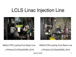
MDL from Sector 0 Sector 20 RF Distribution LO and 102MHz resync by adjusting 2856MHz PAC while monitoring S21 2856MHz Laser resync with laser PAC while monitoring difference in 119MHz laser and FIDO out
Lab Test SetupReference, PAC, PAD The LCLS RF system duplicated in the lab and used for testing of PADs and PACs. At least two of each frequency generation chassis is built to measure phase noise levels. Most components will have development chassis which can be used as a spare. There is only one Dayle, spare is not in the budget.
LCLS New Reference System Lab Measurements Lab Tests Show Reference System Noise Levels Meet All LCLS Requirements 2856MHz = 70fSrms 2830.5MHz = 70fSrms 25.5MHz = 2pSrms 102MHz = 2pSrms 2856MHz : 22fSrms 10Hz to 10MHz 2830.5MHz : 22fSrms 10Hz to 10MHz John Byrd - LBNL 25.5MHz : 152fSrms 10Hz to 1MHz 102MHz : 281fSrms 10Hz to 10MHz
RF Cable Routing All cables are routed from devices in temperature stabilized area to the centrally located, temperature stabilized, RF Hut in the linac gallery. RFHUT Cables run down through penetration 20-17 which is enclosed by the RF Hut Picture taken from Carl Rago’s Talk
RF System Cables / Specifications LCLS Specifications: Laser, RF Gun – 2.3pS L0A, L0B, L1S, L1X, L2, L3 – 5pS
SLAC Linac RF – New Control The new control system will tie in to the IPA Chassis with 800W of drive power available. The RF Reference will be from the new RF reference system. Solid State Sub-Booster PAC I and Q will be controlled by the PAC chassis, running 16bit DACs at 102MHz. Waveforms to the DACs will be set in an FPGA through a microcontroller running EPICS on RTEMS. Existing System
Linac 21-1 Test Set-up Power Coupled out from 476MHz MDL drives a 476MHz Amplifier which feeds a 6X Multiplier from 476MHz to 2856MHz. The 2856MHz out drives both the LO generator and the PAC. The 2830.5MHz LO and 102MHz CLK Generator supplies the LO and CLK to the PAD. A CLK output of the PAD drives the PAC CLK. The PAC output drives the SSSB. The SSSB drives the existing IPA chassis The klystron output coupler is used to measure phase and amplitude with the new PAD.
Linac 21-1 Test Results Tests were done in the gallery with no temperature regulation on cables. Average RMS value of 2 second sliding average is 0.068 degrees. Exponential Smoothing Yields the Following Results. Lowest noise is with a time constant of about 2 points.
LLRF Commissioning – no high power RF, no beam • Low Level Lab Tests and Calibration PACs and PADs • Set at Operational Temperature • PAC Tests and Calibration – SSB Modulator : Set offsets and gain • PAD Tests • ADC Board – SNR Cross Talk – Sine Wave histogram • Chassis – Two Tone or Single Tone - SNR, Noise Floor, IP3 • Installation of PACs and PADs – Other systems required to be complete • LLRF Racks - installed • Water System • Trigger system • AC Rack power • Test RF Cables - Measure Attenuation and Phase Stability • Installation of Solid State Sub-Boosters (SSSB) • Installation of RF VME Crate • Installation of network switches • Get devices booting from afsnfs2 • Test VME connectivity to PAD by sending I and Q avgs. • Connection of PADs, PACs, and VME IOCs to network • Initial Set-up of PAC triggers • Align 119MHz trig to 102MHZ clocks for PACs and PADs • PAD Calibrations • Enter channel calibration factors (APCs, Power Scale Factors – coupler ratios…) • PAC Calibration • Calibration with spectrum analyzer • Calibration with PAD channel • Phase Noise Measurements • 102MHz Clock : 2830.5MHz LO : 2856MHz RF : Laser Lock to RF
LLRF Commissioning - high power RF, no beam • Timing System setup • Line up PAC and PAD triggers to existing modulator triggers • Adjust PAC waveforms for 6 Klystron stations • Adjust PAD window length and offset to fit waveform • Commission local Feedback loops • Gun Tune • Gun Phase • Gun Amplitude • L0A Phase • L0A Amplitude • L0B Phase • L0B Amplitude • Tcav Phase • Tcav Amplitude • L1S Phase • L1S Amplitude • L1X Phase • L1X Amplitude • Test Standby Timing and BCS functions
LLRF Commissioning - high power RF, with beam • Timing System setup • Adjust PAC and PAD triggers to align waveforms to beam time • 119MHz PAD/PAC triggers must move in increments of 14 ticks to keep all phases aligned (~117.6nS). • PAD window must move in increments of four 102MHz cycles to keep phase reading the same. (~39.2nS). Increments of 9.8nS will cause 90 degree phase shifts in readings. • Commission local Feedback loops • Gun Phase - Phase to beam (Rotate phase to get max beam energy) • Gun Amplitude - Check Cal (RF power to maximum energy gain) • L0A Phase - Phase to beam • L0A Amplitude - Check Cal • L0B Phase - Phase to beam • L0B Amplitude - Check Cal • Tcav Phase - Phase to Beam • Tcav Amplitude - Check Cal • L1S Phase - Phase to Beam • L1S Amplitude - Check Cal • L1X Phase - Phase to Beam • L1X Amplitude - Check Cal
High Level Applications • Generic • Correlation plots • Calibration of power levels using beam energy • Distribution System • Rotate Phase 360 degrees • Monitor Phase Errors in Dividers • Correct Divider Phase Errors • PAC • Calibration Mode Operation • Generate and Load Waveforms • Panels for Phase and Amplitude Adjustment • PAD Testing • Crosstalk, SNR, Noise Floor • Sine Wave Histogram • Panels for Phase and Amplitude Monitoring • Local Feedback Control Panels