Download
1 / 38
380 likes | 589 Vues
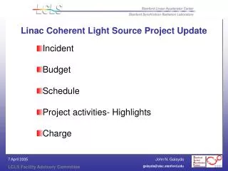
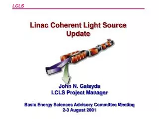
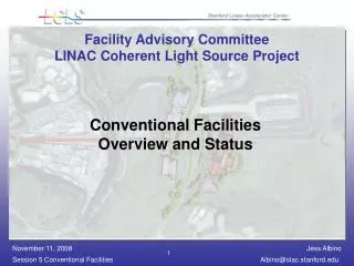
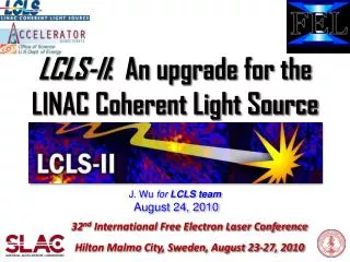
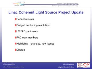
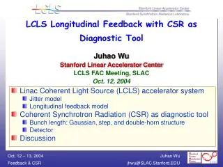
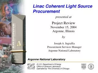
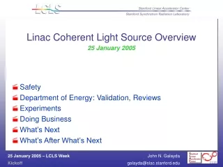
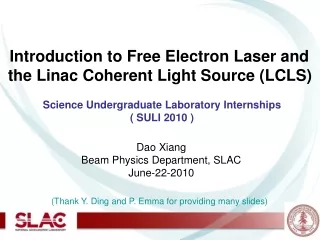
ANL. LLNL. UCLA. The LCLS at SLAC Linac Coherent Light Source. J. B. Hastings (for the LCLS group) January 31, 2007. LCLS. 2 compressors. one undulator. LCLS. X-FEL based on last 1-km of existing SLAC linac. 1.5-15 Å. Beam Transport from Linac Through X-Ray Halls.

E N D
ANL LLNL UCLA The LCLS at SLAC Linac Coherent Light Source J. B. Hastings (for the LCLS group) January 31, 2007 LCLS
2 compressors one undulator LCLS X-FEL based on last 1-km of existing SLAC linac 1.5-15 Å
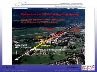
Beam Transport from Linac Through X-Ray Halls Beam Transport Hall: 227-m, above-grade facility to transport electron beam Undulator Hall: 170-m, underground tunnel housing undulators Electron Beam Dump: 40-m long underground facility to separate electron and x-ray beams Near Experimental Hall: underground facility to house 3 experimental hutches, prep, and shops X-Ray Trans. & Diag. Tunnel: 210-m long underground tunnel to transport photon beams from NEH to FEH Front End Enclosure: 40-m long underground facility housing photon beamdiagnostic equipment Far Experimental Hall: underground 46’ cavern housing 3 experimental hutches and prep space
250 MeV z 0.19 mm 1.6 % 4.30 GeV z 0.022 mm 0.71 % 13.6 GeV z 0.022 mm 0.01 % 6 MeV z 0.83 mm 0.05 % 135 MeV z 0.83 mm 0.10 % Linac-X L =0.6 m rf= -160 Linac-0 L =6 m rf gun L0-a,b Linac-3 L 550 m rf 0° Linac-1 L 9 m rf -25° Linac-2 L 330 m rf -41° 25-1a 30-8c 21-3b 24-6d ...existing linac 21-1 b,c,d undulator L =130 m X BC1 L 6 m R56 -39 mm BC2 L 22 m R56 -25 mm DL1 L 12 m R56 0 DL2 L =275 m R56 0 Commission in Jan. 2008 Commission in Jan. 2007 SLAC linac tunnel research yard LCLS Accelerator Schematic
LCLS Installation and Commissioning Time-Line Drive-Laser Commissioning LTU/und. Install LTU/und. hall “ready” Drive-Laser Installed Controls Checkout First Spont. Light A S O N D J F M A M J J A S O N D J F M A M J J 2006 2007 2008 Gun/Inj./BC1 Install (8/21 – 2/20) Gun/Inj./BC1 Commissioning Inj./Linac/BC2 Commissioning linac/BC2 Install LTU/und. Commissioning Oct. 19, 2006
LCLS Installation and Commissioning Time-Line Drive-Laser Commissioning LTU/und. Install LTU/und. hall “ready” Drive-Laser Installed Controls Checkout First Spont. Light A S O N D J F M A M J J A S O N D J F M A M J J 2006 2007 2008 Gun/Inj./BC1 Install (8/21 – 2/20) Gun/Inj./BC1 Commissioning Inj./Linac/BC2 Commissioning linac/BC2 Install LTU/und. Commissioning Oct. 19, 2006
gey= 1.06 μm Emittance Measurements with ‘Quad-Scan’ on OTR Screen OTR screen 95% area cut Gaussian used only as visual aid here 135 MeV, 1 nC, 100 A
Projected Emittance Below 1 μm at 0.7 nC gex = 0.76 μm Q = 700 pC gey = 0.85 μm
Emittance Measured Over 8 Hours gex gey 0.7 nC, 135 MeV, 70 A
x & yemittance1.2 μm at 1 nC charge (design) <1.5% rms charge stability (design is 2%) Drive laser 98% up-time with 500 μJ (250 design) Bunch compression in BC1 fully demonstrated Accelerated LCLS beam to 16 GeV (13.6 design) X-band & 2 RF deflectors both operational New RF performing within spec (e.g., <0.1º rms) Feedback ON: launch, charge, energy, RF, & sz Robust, high-quality RF gun demonstrated Commissioning Results
t= t=0 Science Opportunities Atomic, molecular and optical science (AMOS) Nano-particle and single molecule coherent x-ray imaging (CXI) Coherent-scattering studies of nanoscale fluctuations (XCS) Diffraction studies of stimulated dynamics (pump-probe) (XPP) High energy density science (HEDS) SLAC Report 611 Aluminum plasma classical plasma G G =1 =10 dense plasma G =100 high den. matter - 4 1 - 2 2 4 10 10 10 10 Density (g/cm-3)
Very-intense, ultrashort x-ray pulses will interact with matter in new ways. Atomic strong-field effects may alter the properties of the materials. Atomic, molecular, and optical (AMO) physics
- Ip - Ip 10x20 W/cm2 1015 W/cm2 - Ip 1013 W/cm2 Low-Frequency Physics → High Frequency IR: Low frequency regime VUV FEL: Intense photon source XFEL FEL: Highly ionizing source • Angstrom wavelength • Direct multiphoton ionisation • Secondary processes • Keldysh parameter >>1 • Multi-photon ionisation • Ponderomotive energy 10 meV • Keldysh parameter <<1 • Tunnel / over the barrier ionisation • Ponderomotive energy 10 – 100 eV Optical Frequency = (Ip/2Up)1/2 -1; Up=I/4ω2 (au) Tunneling Frequency
Microscopy image sample light • depth of field limit • lens-limited • direct lens Diffractive imaging Diffraction Microscopy • No depth of field limit • No lens-limited • Computer-limited Coherent-light Known: k-space amplitude: I Support (outline of the object) in real space s CCD Imaging with coherent x-rays
X-ray free-electron lasers may enable atomic-resolution imaging of biological macromolecules One pulse, one measurement Particle injection 10-fs pulse Noisy diffraction pattern Combine 105-107 measurements Classification Averaging Orientation Reconstruction H. Chapman
Motivation for even shorter x-ray pulses Further e- compression difficult: Radiation damage interferes with atomic positions and the atomic scattering factors • CSR in bends • Undulator wakefields Janos Hajdu Dt /fsec Coulomb Explosion of Lysozyme (50 fs)
1 micron SEM of structure etched into silicon nitride membrane First image reconstructed from an ultrafast FEL diffraction pattern 1st shot at full power 2nd shot at full power Reconstructed Image – achieved diffraction limited resolution! Wavelength = 32 nm Chapman et al. Nature Physics (2006) 1 micron Edge of membrane support also reconstructed
LCLS Nanocrystal of lysozyme 5x5x5 LYSOZYMES 1 LYSOZYME
Dynamics Silica: 2610 Å, ΔR/R=0.03, 10 vol% in glycerol, T=-13.6C, 56000 cp sample CCD 22µm direct illumination 1k x 1k CCD 1 MHz ADC 1 s exposure 4 s overhead today: 1 s V. Trappe and A. Robert
XPCS Science Split & Delay High Time–average Brilliance Rep. Rate 120 Hz Sequential Mode High Peak Brilliance Short pulse duration 100fs Dedicated 2D-Detector LCLS Parameters Transverse Coherence 8 and 24 keV
Ultrafast XPCS • Peak Brilliance & Pulse Duration • pulse duration < tC< several ns • Large Q’s accessible
Split and Delay • Provided by DESY/SLAC MoU • Prototype existing • 1st Commissioning May 2007 • pulse duration < delay < 3 ns • based on Si(511) with 2θ= 90º • E=8.389 keV
Traditional Pump-probe • Delay will be achieved by optical delay and/or RF phase shift • Resolution limited by LCLS/laser jitter ~ 1 ps limit
Short Pulse Laser Excitation Impulsively Modifies Potential Energy Surfaces Non-thermal melting of InSb Coherent phonons in Bi
Ultrafast X-ray Scattering Provides Direct Access to Atomic Motion on non-Equilibrium Potential Energy Surfaces …characterizes the shape of the potential A. Lindenberg, et al.Science 308, 392 (2005). D.M. Fritz, et al.Science 315, 633 (2007).
0 -300 -200 -100 100 SLFC LFC RPA -20 0 -60 -40 High brightness of LCLS will enable unique studies of in situ material failure Current: Post Processing x-ray scattering Future: Measure during pressure pulse Simulated x-ray scattering Shocked and incipiently fractured single crystal Al slug Bound e- Shift RPA Particle data SLFC LFC Free e- Te Energy shift (eV) APS Beam LCLS 3-D x-ray tomographic reconstruction of dynamic fracture Multiple and single bunch x-ray scattering from shock recovered samples in progress Collective • LCLS will provide unprecedented fidelity to measure dynamics of the microstate with sub-picosecond resolution • Diffraction lattice compression and phase change • SAXS sub-micron defect scattering • Diffuse dislocation content and lattice disorder R. Lee
Current Status Simulation Classical scattering • MD simulation of FCC copper Periodic features average distance between faults Diffuse scattering from stacking fault Peak diffraction moves from 0,0 due to relaxation of lattice under pressure 0 0 • X-ray diffraction image using LCLS probe of the (002) shows in situ stacking fault information LCLS enables real-time, in situ study of deformation at high pressure and strain rate Future with LCLS Unique capabilities • Imaging capability • Point projection imaging • Phase contrast • High resolution (sub-µm) • Direct determination of density contrast • Diffraction & scattering • Detection of high pressure phase transitions • Lattice structure, including dislocation & defects • Liquid structure • Electronic structure • Ionization • Te, f(v) These complement the standard instruments, e.g., VISAR and other optical diagnostics
2109 photons 380 as Attosecond Pulses Impact: X-ray pulses 500 times shorter than nominal LCLS (2-fsec already in baseline) Lag: 1 yr Level: Straightforward – Spoiler wakefield needs checking Ref:PRL 92:074801,2004, SLAC-PUB-10712. Be foil in BC2 chicane • Parameters: • <400 attosecond pulses • 2109 photons/pulse • 100 pC bunch charge SLAC Contacts: P. Emma, Z. Huang, et al.
LCLS with Multiple Beamlines 535 m 330 m FFTB m-shielding 62 m 100 m Note: Design Hall A and Hall B compatible with LCLS II Expansion
Multiple Undulators and Fast Multi-Bunch Switching Impact: Converts LCLS into a user facility with extended wavelength range, shorter pulses, and enhanced power levels Lag: ~10 yrs Level: Challenging – need multi-bunch E-compensation (variable spacing) Ref:SLAC-PUB-10133. 4.9 ns up to 60 bunches (same again on North side) • Parameters: • 1 to 60 bunches/RF pulse • Up to 8 undulators • Wavelengths below 1 Å? • Pulse lengths to 1 fsec SLAC Contacts: F.-J. Decker, P. Emma, et al.
13.6 GeV Long-Wavelength FEL Impact:Provide soft x-ray FEL in addition to hard x-rays Lag: ~5 yrs Level: Moderate Ref: (none yet) 10-50 Å 250 MeV 1.5-15 Å • Parameters: • I =3.4 kA • 1.2 mm-mrad emittance • σδ = 1x10⁻⁴ • β= 25m • λu = 10 cm • K = 5~12 • B= 0.53~1.28 T • λr = 10 -50 Å • Adjustable-Gap Undulator • Simultaneous Operation with 1.5-Å, but ½-rate SLAC Contacts: J. Arthur, J. Hastings, Z. Huang, PE
2 compressors one undulator LCLS X-FEL based on last 1-km of existing SLAC linac 1.5-15 Å ?
LCLS Future Options: 27 GeV,ge= 0.8 mm, 6.0 kA: 14 GeV, ge = 1.2 mm, 3.4 kA: 27 GeV LCLS XFEL LCLS soft LCLS nom. • The SLAC linac can explore and reach the limits of FEL performance: • Peak brightness • Fluence • Pulse duration • These limits are primarily determined at LOW energy: • Gun • Bunch compression • This is an extraordinary scientific opportunity • Near- and long-term payoff Peak Brightness (phot./s/mrad2/mm2/0.1%-BW) Photon Energy (eV)
By-Pass Line to Long-Wavelength FEL Impact:Provide soft x-ray FEL in addition to hard x-rays Lag: ~5 yrs Level: Moderate (use e+ PEP-II by-pass line) Ref: (none yet) ESA PEP-II e+ by-pass line 10-50 Å 250 MeV 4.3 GeV 10-50 Å 1.5-15 Å pulsed dipoles Parameters: ESB • Adjustable-Gap Undulator • Simultaneous Operation with 1.5-Å, but ½-rate • Possible after-burner undulator added • Possible locations: • Endstaion A or B SLAC Contacts: J. Arthur, J. Hastings, Z. Huang, PE
Circular Polarization for Soft x-rays Impact: Provide variable polarization in the 1-5 nm wavelength range Lag: ~5 yrs Level: Moderate – new undulator Ref:none yet ~ 2 GW (linear polarized) planar helical Two sections Six 3.4m sections ~ 20 GW (90% circular polarized) Parameters: • Parameters: • Electron energy 4.3 GeV • 1.2 mm-mrad emittance • Energy spread 1 MeV • Standard LCLS undulator Contacts: Y. Ding, Z. Huang
30 fs Two-Stage SASE FEL Impact: Short pulse, or narrow bandwidth, & wavelength is more stable Lag: ~5 yrs Level: Moderate – new undulator line or upgrade Ref:SLAC-PUB-9370, TESLA-FEL-97-06E, SLAC-PUB-9633, SLAC-PUB-10310 30 Parameters: Contacts: C. Pellegrini
eN = 1.2 mm P = P0 eN = 2.0 mm P = P0/100 courtesy S. Reiche Final Comments For LCLS, slice emittance >1.8mm will not saturate FEL… SASE FEL is not forgiving— instead of mild luminosity loss, power nearly switches OFF electron beammustmeet brightness requirements