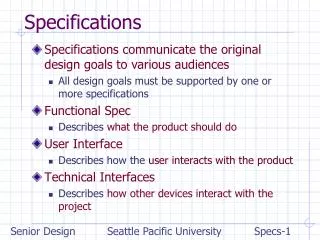

Requirements for Specification Techniques in Embedded Systems
E N D
Presentation Transcript
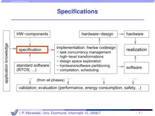
Specification of embedded systems: Requirements for specification techniques (1) • HierarchyHumans not capable to understand systemscontaining more than ~5 objects.Most actual systems require more objects Hierarchy • Behavioral hierarchyExamples: states, processes, procedures. • Structural hierarchyExamples: processors, racks,printed circuit boards proc proc proc
Specification of embedded systems: Requirements for specification techniques (2) • Timing behavior. • State-oriented behaviorRequired for reactive systems;classical automata insufficient. • Event-handling(external or internal events) • No obstacles for efficient implementation
Requirements for specification techniques (3) • Support for the design of dependable systemsUnambiguous semantics, ... • Exception-oriented behaviorNot acceptable to describe exceptions for every state. We will see, how all the arrows labeled k can be replaced by a single one. .
Requirements for specification techniques (4) • ConcurrencyReal-life systems are concurrent • Synchronization and communicationComponents have to communicate! • Presence of programming elementsFor example, arithmetic operations, loops, and function calls should be available • Executability (no algebraic specification) • Support for the design of large systems ( OO) • Domain-specific support
Requirements for specification techniques (5) • Readability • Portability and flexibility • TerminationIt should be clear, at which time all computations are completed • Support for non-standard I/O devicesDirect access to switches, displays, ... • Non-functional propertiesfault-tolerance,disposability, EMC-properties, weight, size, user friendliness, extendibility, expected life time, power consumption... • Adequate model of computation
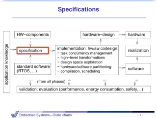
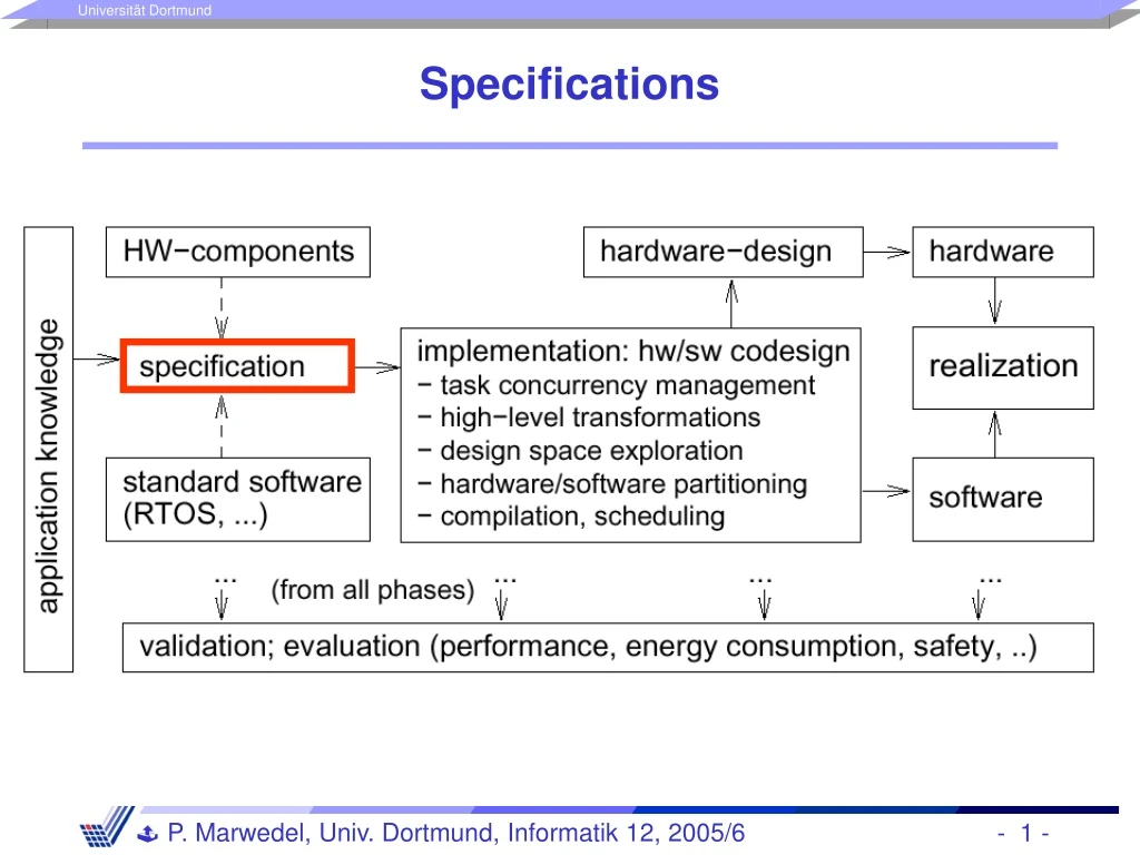
Models of computation- Definition - • Models of computation define [Lee, UCB, 1999]: • What it means to be a component: Subroutine? Process? Thread? • The mechanisms by which components interact:Message passing? Rendez-vous? • Possibly also:What components know about each other(global variables? Implicit behavior of other components) • Certainly not:vocabulary
a:=5 b:=7 c:=8 a:=6 a:=9 Models of computation- Examples (1) - • Communicating finite state machines (CFSMs): • Discrete event model queue 5 6 a b c 5 10 13 15 19 time action 7 8
Models of computation- Examples (2) - • Asynchronous message passing • Differential equations • Synchronous message passing Ptolemy simulations?
Facing reality • No language that meets all language requirements using compromises
StateCharts: recap of classical automata • Classical automata: input X Internal state Z output Y clock Moore- + Mealy automata=finite state machines (FSMs) Next state Z+ computed by function Output computed by function e=1 Z0 Z1 • Moore-automata:Y = (Z); Z+ = (X, Z) • Mealy-automataY = (X, Z); Z+ = (X, Z) 0 1 e=1 e=1 Z3 Z2 2 3 e=1
StateCharts • Classical automata not useful for complex systems (complex graphs cannot be understood by humans). • Introduction of hierarchy StateCharts [Harel, 1987] • StateChart = the only unused combination of • „flow“ or „state“ with „diagram“ or „chart“
FSM will be in exactly one of the substates of S if S is active(either in A or in B or ..) Introducing hierarchy
Definitions • Current states of FSMs are also called active states. • States which are not composed of other states are called basic states. • States containing other states are called super-states. • For each basic state s, the super-states containing s are called ancestor states. • Super-states S are called OR-super-states, if exactly one of the sub-states of S is active whenever S is active. superstate ancestor state of E substates
Default state mechanism • Try to hide internal structure from outside world! • Default state • Filled circleindicates sub-state entered whenever super-state is entered. • Not a state by itself!
History mechanism • For input m, S enters the state it was in before S was left (can be A, B, C, D, or E). If S is entered for the very first time, the default mechanism applies. • History and default mechanisms can be used hierarchically. (behavior different from last slide) k m
Combining history and default state mechanism same meaning
Concurrency • Convenient ways of describing concurrency are required. • AND-super-states: FSM is in all (immediate) sub-states of a super-state; Example:
Entering and leaving AND-super-states • Line-monitoring and key-monitoring are entered and left, when service switch is operated. incl.
Types of states • In StateCharts, states are either • basic states, or • AND-super-states, or • OR-super-states.
Timers • Since time needs to be modeled in embedded systems, • timers need to be modeled. • In StateCharts, special edges can be used for timeouts. If event a does not happen while the system is in the left state for 20 ms, a timeout will take place.
event [condition] / reaction General form of edge labels • Events: • Exist only until the next evaluation of the model • Can be either internally or externally generated • Conditions: • Refer to values of variables that keep their value until they are reassigned • Reactions: • Can either be assignments for variables or creation of events • Example: • service-off [not in Lproc] / service:=0
The StateCharts simulation phases (StateMate Semantics) • How are edge labels evaluated? • Three phases: • Effect of external changes on events and conditions is evaluated, • The set of transitions to be made in the current step and right hand sides of assignments are computed, • Transitions become effective, variables obtain new values. • Separation into phases 2 and 3 guarantees deterministic • and reproducible behavior.
Example • In phase 2, variables a and b are assigned to temporary variables. In phase 3, these are assigned to a and b. As a result, variables a and b are swapped. • In a single phase environment, executing the left state first would assign the old value of b (=0) to a and b. Executing the right state first would assign the old value of a (=1) to a and b. The execution would be non-deterministic.
Reflects model of clocked hardware • In an actual clocked (synchronous) hardware system, both registers would be swapped as well. Same separation into phases found in other languages as well, especially those that are intended to model hardware.
phase 1 phase 2 Status phase 3 Steps • Execution of a StateChart model consists of a sequence of (status, step) pairs Status= values of all variables + set of events + current time Step = execution of the three phases (StateMate semantics)
Broadcast mechanism • Values of variables are visible to all parts of the StateChart model. • New values become effective in phase 3 of the current step and are obtained by all parts of the model in the following step. StateCharts implicitly assumes a broadcast mechanism for variables. StateCharts is appropriate for local control systems (), but not for distributed applications for which updating variables might take some time ().
Lifetime of events • Events live until the step following the one in which they are generated („one shot-events“).
Evaluation of StateCharts (1) • Pros: • Hierarchy allows arbitrary nesting of AND- and OR-super states. • (StateMate-) Semantics defined in a follow-up paper to original paper. • Large number of commercial simulation tools available(StateMate, StateFlow, BetterState, ...) • Available „back-ends“ translate StateCharts into C or VHDL, thus enabling software or hardware implementations.
Evaluation of StateCharts (2) • Cons: • Generated C programs frequently inefficient, • Not useful for distributed applications, • No program constructs, • No description of non-functional behavior, • No object-orientation, • No description of structural hierarchy. • Extensions: • Module charts for description of structural hierarchy.
Summary • Requirements for specification languages • Hierarchy • Timing behavior • State-oriented behavior • Concurrency • Synchronization & communication, … • Models of computation • StateCharts • AND-states • OR-states • Timer • Broadcast • Semantics • …