XRT Point Spread Function Andy Read
This study focuses on analyzing 2-D PSFs in different modes and instruments to improve detection of on- and off-axis sources using elliptical profile fitting. It involves parameterization, stacking images, and evaluating elliptical parameters for enhanced source identification.


XRT Point Spread Function Andy Read
E N D
Presentation Transcript
2-D PSFs – ‘MEDIUM’ mode – Images – fn(instr, E, theta, phi) – used in SAS source-searching (generated from SCISIM) 1-D PSFs – ‘EXTENDED’ mode – King profile (r0, alpha) – fn(instr, E, theta) – used in ARF generation/spectral fitting for circular, annular or box regions also… ‘HIGH’ mode – 3-gaussian parametrisation of MEDIUM mode maps. Used in arfgen for irregular shapes or ellipses, etc. Problems with energy dependency ‘LOW’ mode – 1 gaussian, not used anywhere CCF PSFs that are used in SAS:
2-D PSFs – ‘MEDIUM’ mode – Images – fn(instr, E, theta, phi) – used in SAS source-searching (generated from SCISIM) CCF PSFs that are used in SAS: Images for each instrument at various E and Off-axis angle – presently all SCISIM-generated, simple, and all the same for each instrument
PN Energy Off-axis angle EPIC PSF : Determining the on- and off-axis 2-D PSF (last meeting) • 2XMMp source list - select M1, M2, PN point sources that have large numbers of counts, are below pile-up limit, cover full range in off-axis angle (~200 obs) – create calibrated event lists • Clean event files (high-BG, out-FOV etc.), extract source, reject bad fields, create source images (all E-bands, all instruments), subtract other sources, detector-rotate, Gaussian re-centre • Stack good images together for each instrument (3) E-band (8) off-axis angle (6) - clean, BG-subtract stacked images, re-normalize, create CCF-like files Improvements in source-detection for bright on- and off-axis sources Blue: current CCFs Green: New 2-D PSFs
PN Energy Off-axis angle ‘H’
MOS2 Shape non-rotation is not just M2! (just more obvious in M2) All EPIC instruments behave in a similar way! More later….
Use AMR-created azimuthally-stacked 2-D PSF real-data images (for each instrument, energy, off-axis angle) Use CIAO-Sherpa to fit elliptical profile (beta2d) to images Elliptical parameters (core radius, alpha, ellipticity), obtained for each instrument, energy, off-axis angle CCF files produced (RDS) with new ELLBETA PSF CCF extension Numbers/trends/problems currently being reviewed (improvements made… [see later]) To be used in arfgen… New CCF PSF – ELLBETA – Elliptical parametrization of the 2-D PSF
New ELLBETA PSF in CCF R0α ell.
Properties of ELLBETA elliptical parameters: • Variation of r0, alpha, ellipticity with energy and off-axis angle • MOS1 AMR-H PSF (2-D, real data) (last meeting)
Properties of ELLBETA elliptical parameters: • Variation of r0, alpha, ellipticity with energy and off-axis angle • MOS2 AMR-G PSF (2-D, real data, [stretch-stacked]) (last meeting)
Properties of ELLBETA elliptical parameters: • Variation of r0, alpha, ellipticity with energy and off-axis angle • PN AMR-H PSF (2-D, real data) (last meeting)
Status • CCFs, XRT1_XPSF_008, XRT2_XPSF_008, XRT3_PSF_007 made with ELLBETA model • Numbers under review at LU + arfgen/EE testing (RDS/AMR) • Re-stacking, cleaning and re-fitting leads to improvements and smoother functions at high-E, high-theta • Low- & medium-energy EE values look very sensible/consistent e.g. • EE at medium/high E should (theoretically) be higher than at low E • Still more refinements needed? EE too high at v.high E? Looking into this
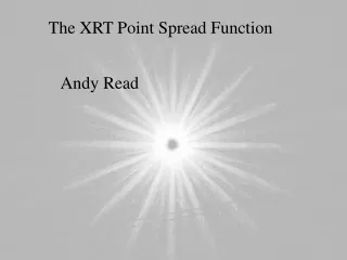
The 2-D PSF GX 339-4 (0204730301)
The 2-D PSF The star-like pattern – the ‘spokes’ – is created by the spider which supports the 58 co-axial Wolter I mirrors of the telescope
PN Energy Off-axis angle EPIC PSF : Determining the on- and off-axis 2-D PSF Spokes in stacked images have been lost …
In PA-corrected DET space, the spokes are not rotated, and keep the same orientation for all EPIC 16 main spokes 22.5° apart (360/16) Offset of 11.25° (22.5/2) i.e. Same effect as MOS2 ‘triangle’ – ‘shape’ is not rotated
Observed spokes are actually due to the gaps between the spider legs, not the legs themselves, which are coincident with the secondary spikes and the dark lanes. Without the spider you would see uniform scattering wings without the radial gaps. Also, some strange, very small misalignments…?
Secondary spokes? Due to scattering at a small level from the sides of the spider legs. Dark lanes? Shadowing must be due to the electron deflector arms which mirror the spider and are mounted after the rear aperture.
Model : Ellipse (PA-rotated, PA-stretched) plus (PA-dependent) cosine-filtered, non-stretched, non-rotated spokes
List of variable parameters in ’07 model Main ellipse [PA-rotated, PA-stretched] Ro, alpha, ellipticity (fn: Instr, Energy, Theta, … Phi?) Spokes [non-rotated, non-stretched, strength-filtered (PA-dependent)] Ro, alpha, width (ellipticity), strength wrt main ellipse Secondary spokes – same considerations, plus strength wrt primary spokes Phi-dependence of strength (e.g. cosine-filtering? Plus S-M asymmetry) But some/all of these parameters may vary w.r.t. e.g. Instr (e.g. M2), Energy, Theta, (Phi)… (plus also Source strength?...) Is there constant spoke-to-main behaviour (and constant secondary spoke-to-primary spoke behaviour)?... Yes (last talk) Some ‘fixed’ parameters? spoke angles (primary & secondary) and offsets However, no single specific example(s?) to fit model to…?
How to move forward? – I (older – last talk) Can’t fill CCF with images for each Instr, Energy, Theta & Phi Don’t have the images/stats to create all image PSFs (need several good, clean, bright, broad-E, non-piled-up sources at all detector positions) CCF files would be Nphi (several 10’s) times larger than at present (& PSF CCF files are already very large indeed) Could have CCF libraries of the 2 components: i.e. Main & Spokes Main - Ro, alpha, ellipticity (fn: Instr, Energy, Theta, … Phi?) Present MEDIUM CCF images, or better still, images created from new ELLBETA? Spokes - Ro, alpha, width (ellipticity), strength wrt main ellipse (fn: ??) New images (non-filtered?) Within the source-searching (or other?) analysis (e.g. in CAL/emldetect): Retrieve (or create?) relevant Main & Spokes images Need to PA-rotate Main and strength-filter Spokes (PA-dependant, plus asymmetric S-M), scale each, and combine.
How to move forward? – II (new, simpler – better) • Stacked images in general work well in emldetect (GL) • Can model these images (and have done - ELLBETA) • Can create idealized images from these models (ellimage) • These however have a smeared azimuthal dependence (created from several sources at different azimuths) [sums to ~elllimage] • Need to (in CAL/CCF/emldetect): • choose the correct ellimage (instrument, off-axis angle, energy) • rotate the ellimage for the detector position of the source (and PA) • ‘add in’ the azimuthal (spoke etc.) dependence (PA-dependant) • e.g. Filter the ellimage azimuthally, retaining overall profile, and including correct angles, offsets etc!
Flat-Topped Triangular Function 22.5° spoke spoke 0.18 Profile needs to be such that no change is introduced to the full (360°) radial profile – i.e. areas need to cancel out This azimuthal function is now used 0.18 1.00 Estimated (from the data) widths of various components
General Azimuthal Dependency What causes the MOS2 effect? Certain (sets of) MOS2 mirror shells are not perfectly circular?
MOS2 (‘h’ - shape conserved, stretch randomized) Θ = 0´ 45% of mean Strong effect! (45%) 3-peaked cosine function fits well (peaks at 50°, 170°, 290°)
MOS2 (‘h’ - shape conserved, stretch randomized) Θ = 3´
MOS2 (‘h’ - shape conserved, stretch randomized) Θ = 6´
MOS2 (‘h’ - shape conserved, stretch randomized) Θ = 9´
MOS2 (‘h’ - shape conserved, stretch randomized) Θ = 12´ Effect still visible/constant, even though random off-axis stretching is present
MOS2 (‘h’ - shape conserved, stretch randomized) Θ = 15´ Effect lost – individual very stretched examples now dominating
MOS1 (‘h’ - stretch stacked [no shape change]) Θ = 0´ Flat profile – no effect
MOS1 (‘h’ - stretch stacked [no shape change]) Θ = 3´
MOS1 (‘h’ - stretch stacked [no shape change]) Θ = 6´ Peaks coming in at 90° & 270°, due to stacked stretch effect. (MOS2 cosine effect shown for comparison)
MOS1 (‘h’ - stretch stacked [no shape change]) Θ = 9´
MOS1 (‘h’ - stretch stacked [no shape change]) Θ = 12´
MOS1 (‘h’ - stretch stacked [no shape change]) Θ = 15´ Very strong peaks at 90° & 270°, due to stacked stretch effect.
PN (‘h’ - stretch stacked [no shape change]) Θ = 15´ Very strong peaks at 90° & 270°, due to stacked stretch effect.
Energy M2 Off-axis angle