XRT Point Spread Function in Slewing Mode
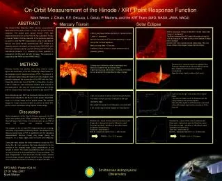
XRT Point Spread Function in Slewing Mode. Off-Axis PSF. A few suitable off-axis sources are now appearing in the XMM archive… Work ongoing… Sources both on- and off-axis… moving sources…. QSO 1308+326 7 arcmin off-axis. AX J1746.3-2843 5.5 arcmin off-axis. SLX 1744-299 ~ 4 arcmin.

XRT Point Spread Function in Slewing Mode
E N D
Presentation Transcript
Off-Axis PSF A few suitable off-axis sources are now appearing in the XMM archive… Work ongoing… Sources both on- and off-axis… moving sources… QSO 1308+326 7 arcmin off-axis AX J1746.3-2843 5.5 arcmin off-axis SLX 1744-299 ~ 4 arcmin SLX 1744-300 ~ 1.5 arcmin NGC7603 10 arcmin off-axis
EPIC PSFs For the Slew & Slow-Slew Survey, Incorporating New Modes Sgr X-3 Sirius • Based on present understanding (from slew event files) • Any arbitrary, straight, constant-speed path of a source through any EPIC detector pn ccd#6 pn ccd#9
PN DETY RAWX DETX 3 2 1 4 5 6 RAWY Slew Direction RAWY SlewY 12 11 10 7 8 9 = SlewX DETX RAWX = SlewY DETY Source Direction SlewX
MOS1 DETY 6 DETX 7 5 RAWY 1 RAWX Slew Direction 2 4 3 SlewY = SlewX DETY = SlewY - DETX Source Direction SlewX
MOS2 DETX 2 7 DETY RAWX 3 6 1 RAWY Slew Direction 4 5 SlewY = SlewX - DETX = SlewY - DETY Source Direction SlewX
2 Main Parameters SlewY b – ‘impact parameter’ β – ‘impact angle’ b β SlewX Also: Slew speed (90°/hr, 30°/hr) Mode (FF, eFF, 3x3) Energy …
Vignetting must be taken into account – central PSFs contribute more to final summed PSF – calculate vignetted-weighted sum MOS1 MOS2
High vignetting MOS1 MOS2 High vignetting Low vignetting DETY DETX Low vignetting
RGAs cause azimuthal variations in off-axis vignetting in the MOSs • MOS2 function is identical • Implies, with exposure maps, detector positions of low/high vignetting
MOS1 DETY 6 DETX 7 5 RAWY 1 RAWX Slew Direction low vig. high vig. RGS1 2 4 3 SlewY = SlewX DETY = SlewY - DETX Source Direction SlewX
MOS2 DETX 2 7 DETY RAWX 3 6 1 ? RAWY Slew Direction low vig. high vig. RGS2 4 5 SlewY = SlewX - DETX = SlewY - DETY Source Direction SlewX
‘Frame-blurring’ – within a single frame the source can travel an appreciable distance Slew Direction • PSF at each point is blurred (stretched) in the slew direction, depending on slew-speed & mode pn extended full frame – ‘frameblur’ of 18 arcseconds
2-D PSFs – ‘medium’ CCF PSFs – Images – fn(instr, E, theta, phi) – used in SAS source-searching 1-D PSFs – ‘extended’ CCF PSFs – King profile (r0, alpha) – fn(instr, E, theta) – used in ARF generation/spectral fitting PSFs that are used :
2-D PSFs – ‘medium’ CCF PSFs – Images – fn(instr, E, theta, phi) – used in SAS source-searching
Source path calculated (e.g. b=5500, β=25°, for MOS1, Full-Frame, slew-speed=90°/hr) • Step through n small intervals of source path – Is the source on the detector (Y/N)? • For each ‘Y’ - Interpolate and rotate appropriate PSF (position, energy, instrument, mode etc.) from CCF 2-D images (512 x 512, 1.1“) - Obtain vignetting (pos, E, instr. etc.), and weight PSF image by vignetting - Stretch PSF for ‘frameblurring’ (instrument, mode, slew-speed) • Add PSFs for whole source path and normalise 2D image (512 x 512, 1.1“) (sum over image = 1) • MOS1, Full-Frame, slew-speed=90°/hr - 4′ PSF – unusable… Image log-scaled to enhance low-SB features
MOS1 • 3x3 mode • slew-speed=30°/hr • 12“ PSF – very usable…
Need for Vignetting : • e.g. PN, b=13500, β=-45°, for PN, Full-Frame, slew-speed=30°/hr) • Larger contribution from off-axis PSFs (elongation in perpendicular-to-slew direction) when vignetting not correctly taken into account No Vignetting Vignetting
Loss of CCD6 • MOS1 • 3x3 mode • slew-speed=30°/hr • Loss of CCD6 causes shape change in 2-D PSF
100" • MOS2 • 3x3 mode • slew-speed=30°/hr • 12“ PSF blurring • Outer parts of PSF due to off-axis PSFs • Inner parts of PSF due to frameblurring
pn • e.g. b=-17000 β=5° • (zoom-in on PSF) • All PSFs compact (short frame times) • FF 30°/hr best • eFF 30°/hr ≈ FF 90°/hr pn, FF, 90°/hr, FB:6.6" pn, FF, 30°/hr, FB:2.2" pn, eFF, 30°/hr, FB:6.0"
CCF Files • Possible CCF 2-D PSF images • For each instrument, mode, energy… 2-D PSF as Function of b (impact parameter) • If β (impact angle) not equal to ~0, then would need several times more images as function of b and β
CCF Files • Possible CCF 2-D PSF images • For each instrument, mode, energy… 2-D PSF as Function of b (impact parameter) • If β (impact angle) not equal to ~0, then would need several times more images as function of b and β • (note large ‘jump’ in PSF shape at edges of detector as path moves from 1 CCD to 3 CCDs)
2-D PSFs – ‘medium’ CCF PSFs – Images – fn(instr, E, theta, phi) – used in SAS source-searching 1-D PSFs – ‘extended’ CCF PSFs – King profile (r0, alpha) – fn(instr, E, theta) – used in ARF generation/spectral fitting
Source path calculated (e.g. b=0, β=0°, for MOS2, 3x3 mode, slew-speed=30°/hr) • Step through n small intervals of source path – Is the source on the detector (Y/N)? • For each ‘Y’ - Obtain 1-D King parameters (r0, alpha) (position, energy, instrument) from CCF - Create a 2-D image of (circular) PSF - Obtain vignetting (pos, E, instr. etc.), and weight PSF image by vignetting - Stretch PSF image for ‘frameblurring’ (instrument, mode, slew-speed) • Sum weighted PSFs for whole source path • Fit 2D summed PSF image with a King profile to give r0, alpha for whole source path • Note: frameblurred PSFs are now non-circular (visible?) – Fitted King profiles look very good • Vignetting – King parameters of final PSF are closer to those of central PSF than edge PSFs • Frameblurred PSFs are wider (larger r0, flatter alpha) than the non-FB PSFs
r0 and alpha as function of impact parameter • impact angle=0, energy=2keV • All examples: pn FF, MOS 3x3, 30°/hr • Actual CCF parameters PN MOS1 MOS2 (no CCD6)
r0 and alpha as function of impact parameter (zoom) • impact angle=0, energy=2keV MOS1 MOS2 (no CCD6)
r0 and alpha as function of impact angle • impact parameter=0, energy=2keV PN MOS1 MOS2 (no CCD6)
r0 and alpha as function of impact angle (zoom) • impact parameter=0, energy=2keV MOS1 MOS2 (no CCD6)
r0 and alpha as function of energy • impact parameter=0, impact angle=0 PN MOS1 MOS2 (no CCD6)
r0 and alpha as function of energy • impact parameter=10000, impact angle=0 PN MOS1 MOS2 (no CCD6)
Slew speed = 90°/hr : on-source time <~12 s (mean ~8 s) Slew speed = 30°/hr : on-source time <~36 s (mean ~24 s) Tangential projection not valid over whole slew. Long slews need to be subdivided to maintain astrometry. Divide slew into ~1 deg2 images and recalculate sky positions. Source search using near-standard pipeline tuned for ~zero background + New CCF files
Slew source encircled energy & ARFs etc. calculated using sky co-ordinate images…
Detector-Sky issues ? • For pointed observations, sky and detector images are closely related… for slews, this may not be the case… • When the source-searching finds a candidate source, how does it know what PSF is appropriate (i.e. what b, β) ? • Similarly for arfgen – how does it know what the appropriate PSF is ?
Closing thoughts… • Azimuthal MOS-RGA vignetting variations not included • Will β always be ~0? If not, may need a whole extra dimension of CCF entries (easy to produce)
Slewing-mode PSFs (1-D & 2-D) calculated using current CCF pointed PSFs • Improvements in pointed PSFs, especially off-axis (ongoing) lead easily & directly to improved slewing-mode PSFs QSO 1308+326 7 arcmin off-axis AX J1746.3-2843 5.5 arcmin off-axis SLX 1744-299 ~ 4 arcmin SLX 1744-300 ~ 1.5 arcmin NGC7603 10 arcmin off-axis