Download
1 / 10
110 likes | 280 Vues
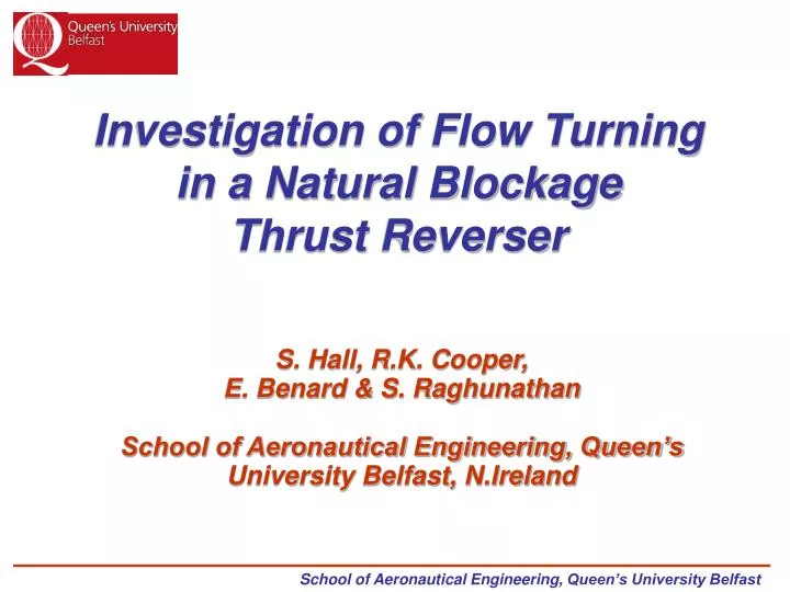
Investigation of Flow Turning in a Natural Blockage Thrust Reverser. S. Hall, R.K. Cooper, E. Benard & S. Raghunathan School of Aeronautical Engineering, Queen’s University Belfast, N.Ireland. Thrust Reversers are used to :- Provide extra safety margin during landing and aborted take offs.

E N D
Investigation of Flow Turning in a Natural Blockage Thrust Reverser S. Hall, R.K. Cooper, E. Benard & S. RaghunathanSchool of Aeronautical Engineering, Queen’s University Belfast, N.Ireland
Thrust Reversers are used to :- Provide extra safety margin during landing and aborted take offs. Expedite ground manoeuvring at congested airports. Natural Blockage Cascade Fan Flow Reverser (CF34-8C, CRJ-700)
Model Geometry CF34-8C (Reverser Deployed) Simplified Model Geometry
Testing at full-scale engine conditions is costly and requires sophisticated test facilities and equipment. M=0.4 M=0.1 Why Low-Speed Testing? • Computational Studies suggest that compressibility effects are not dominant.
Experimental Model • Experiment Features:- • 50% scale duct. • Test Section: 380mm by 89mm • Max Inlet Vel: 13.3m/s
Computational Analysis • Computational Model Features:- • Unstructured mesh (46726 cells) • Farfield boundaries: 20 model lengths upstream/vertically • 10 model lengths downstream • Entrainment flow on upstream wall • Solution:- • 2D, incompressible steady, 1st order • Reynolds Averaged Navier-Stokes equations (RANS) • RNG K- turbulence model.
Results for Surface Static Pressure Coefficient Duct Upper Surface Duct Lower Surface
Results for cascade post-exit pressure rake (NPR=1.0033) Velocity vectors at rake position Rake total pressure coefficient
Comparison of Experimental/CFD data (NPR=1.0033) Static Pressure Coefficient Bottom Wall Static Pressure Coefficient Upper Wall
Experiment successfully models qualitative aspects of flow through the reverser despite low nozzle pressure ratios. Conclusion • 2D CFD results show that 3D effects and flow separation in reverser • flow are significant. 3D model simulations recommended.