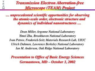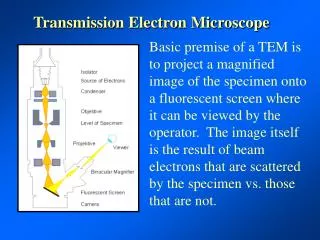
The Transmission Electron Microscope
The Transmission Electron Microscope . Bob Ashley 6- 21 -2013. Overview. Systems of the TEM Illumination Condenser lens system Specimen manipulation stage Imaging system Image formation Magnification Recording system. Reading List.

The Transmission Electron Microscope
E N D
Presentation Transcript
The Transmission Electron Microscope Bob Ashley 6-21-2013
Overview • Systems of the TEM • Illumination • Condenser lens system • Specimen manipulation stage • Imaging system • Image formation • Magnification • Recording system
Reading List Practical Electron Microscopy for Biologists. G. A. Meek.
The Transmission Electron Microscope Bizzola Electron Microscopy 1999
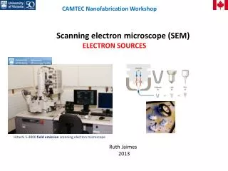
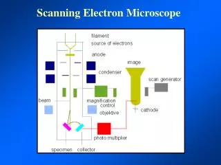
Illumination SystemThermionic Emission Source • Electron source or gun • Provides first coherent crossover of electron beam • High voltage leading to filament- heated metal wire (cathode) • Tungsten or Lab6 (lanthanum hexaboride) • Work function • Energy necessary to bring about electron emission • Electrons would have no order • Wehnelt Cap • Electrode that shapes and controls emission • Negative relative to filament • Anode • Positive respective to filament Wikipedia
Source Types • Tungsten • Wire filament • Lab6 • Lanthanum hexaboride crystal • Field Emission Gun • Tungsten tip • Thermionic (Schotkky) and Cold
Field Emission Source Allows for emission of electrons from fine tip via charge differential of tip and anodes. Brighter More coherent source Atomic diameter point source is future of FE guns
Coherent or Incoherent • Coherent • Waves have same wavelength and phase, in the ideal sense would be perfectly coherent • Incoherent • Waves have modulating phase relationships and wavelengths • Temporal coherency • Wavelength differential • Spatial coherency • Size of source Temporal coherence length= product of velocity and planks constant divided by the energy spread Spatial coherence length= wavelength divide by 2 times the alpha (angle formed from source at at the specimen)
Condenser Lenses C1 is spot size Determines size of beam on specimen C2 is beam brightness knob Varies and magnifies C1 Aperture is a physical aperture in range of sizes Reduces spherical aberration Associated stigmator to correct astigmatism C1 Crossover www.ammrf.org.au/ www.matter.org.uk/
Specimen Chamber Vacuum interlock system www.ammrf.org.au
Specimen Holder and Stage • Holds sample in place on top of copper grid • Moved with stage in x,y,z • Tilting holder • Side or top entry • Room temperature • Cryo holder
Grid Types • Supports used must be strong yet electron transparent • Plastic (formvar) • Carbon • Holey carbon • Quantifoil • C-flat
Image Formation • Four fundamental processes • Scattering • Absorption • Gives rise to amplitude contrast • Contrast from absence of electrons • Diffraction • Used to enhance contrast in cryoEM but with loss of resolution • Interference • Gives rise to phase contrast • Halo or fringe around object
Specimen Beam Interactions: Scattering • Elastic (Rutherford scattering) • Electron collides with or passes close to a nucleus of atom, no loss of energy of initiating electron • changes direction without losing velocity or energy • Inelastic • Electron collides with cloud electrons, measurable loss of energy of initiating electron • As sample thickness increases more electrons are backscattered • Assumed to occur only once in TEM (either the e- scatters or it doesn’t) • Sometimes referred to as the direct transmitted beam if no scattering occurred • Can either forward or back scatter • Scatter measured in spatial deviation manifests as contrast, scatter of angular deviation manifests as diffraction patterns
Coherence • Electrons remain in phase with one another after passing through sample • Incoherent electrons are those that have no consistent phase relationship upon passing through sample • Elastic • Usually coherent • Inelastic • Almost always incoherent Scattering and Coherence
Accelerating Voltages • How does this all relate in choice of your electron accelerating voltage or kV? • The faster the speed of the electrons the better resolution obtained • But at the sacrifice of contrast • Slower electron speeds have more opportunity for inelastic scattering, inelastic scattering produces energy (heat) therefore lower kV has more specimen damage
Mass Thickness Typical thick sections are at 100nm while high resolution is limited to 10’s of nm.
Objective Lens • Most important lens • Forms initial image further magnified by other lenses • Responsible for focus • Blocking of more peripherally deflected electrons with Objective aperture • The larger the aperture used the more phase contrast • Important for cryo EM and higher resolution • The smaller the aperture the more aperture contrast • Associated stigmator to correct any astigmation
Objective Aperture Bozzola 176
Similar in construction to objective lens Major function is to assist in the magnification of the image from the objective lens Intermediate and Projections Lenses
Next Week: CCDs and their function in the electron microscope