Download
1 / 21
210 likes | 347 Vues
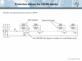
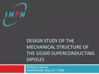
Design study of the mechanical structure OF the SIS300 superconducting dipoles. Stefania Farinon WAMSDO08, May 22 nd 2008. Introduction. SIS300 dipole is pulsed (1.5-4.5 T ) At a high field rate (1 T /s) For 10 7 cycles. Main issue is fatigue. SIS300 dipole mechanical structure.

E N D
Design study of the mechanical structure OF the SIS300 superconducting dipoles Stefania FarinonWAMSDO08, May 22nd 2008
Introduction • SIS300 dipoleispulsed (1.5-4.5 T) • At a high field rate (1 T/s) • For 107cycles Main issue is fatigue
SIS300 dipole mechanical structure collar keys (stainless steel) E=220 GPa winding E=7.5 GPa iron yoke 1 mm lamination E=200 GPa C-clamps (Al alloy) E=80 GPa collars (Nitronic 40) 3 mm laminationE=192 GPa pins (stainless steel)E=220 GPa
collars assembly assembled through pins 3 mm 30 mm
collaring operation total force: 260 tons/m no applied force
Von Mises stress after collaring (MPa) 239 581 209 508 436 179 363 149 120 291 90 218 Nitronic40 yield strength: YS=680 MPa @ 300 K YS=1430 MPa @ 4 K 145 60 73 30 0 0
cool-down and energization of collared-onlywindings (withoutiron) 579 Fx= 0.68 MN/m 510 cool down peak VM stress=175 MPa energization @ 4.5 T peak VM stress=579 MPa =0.35syield (107cycles) 446 Fy=-0.3 MN/m peak stress 382 318 255 smean=(175+579)/2=377 MPa salt=(579-175)/2=202 MPa 100 mm 191 127 64 0
iron yoke constraints The goal is a side containment to collars. We should: • avoid making a second collaring operation on the winding
force to close the iron yoke we decided to limit the force needed to close the iron yoke to 2/3 of the force needed to close the collars: 170 tons/m C-clamps are heatedtobeinsertedwithoutanyapplied force
iron yoke constraints The goal is a side containment to collars. We should: • avoid making a second collaring operation on the winding • take into account the effect of the different thermal contractions of stainless steel and iron
effect of differential thermal contractions(airon~1.8·10-3, aNitronic40~2.4·10-3) • we apply a pre-stress to the collaredcoils through the iron yoke: • C-clamps are made of Al-alloy (aAl alloy~4.3·10-3) 80 mm are removed from the midplane they keep closed the iron yoke
iron yoke constraints The goal is a side containment to collars. We should: • avoid making a second collaring operation on the winding • take into account the effect of the different thermal contraction of iron and stainless steel • limit the fringe field increase
fringe field 230 mm increased from 230 to 240 mm
fringe field 50 gauss r ~ 290 mm r = 240 mm
peak Von Mises stress (MPa) 1.5 T 4.5 T
Conclusions • The mechanical design requiresnecessarilyboth the collars and theironyoketolimit the stresses • The peakstresses (MPa) are: • The fatiguebehaviourisespeciallycritical in this project. The largest stress variation in thecollaris 116 MPa, wellwithin the limit of theSodebergdiagramfor 10 millionscycles