Download
1 / 19
230 likes | 673 Vues
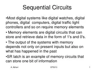
Asynchronous Sequential Circuits aka ‘Feedback sequential circuits’ - Wakerly Chap 7.9. Asynchronous Circuits. Not synchronous - Not clocked – No flipflops. The circuit responds directly to changes in its input signals Circuit design must account for races and hazards. Inputs. Outputs.

E N D
Asynchronous Sequential Circuitsaka ‘Feedback sequential circuits’- Wakerly Chap 7.9
Asynchronous Circuits • Not synchronous - Not clocked – No flipflops • The circuit responds directly to changes in its input signals • Circuit design must account for races and hazards Inputs Outputs State variables Δt
Uses for asynchronous design… • Flipflops (first case below…) • Situations in which synchronous design cannot be used, either because • a clock does not exist, or • it cannot be assumed that all devices are clocked simultaneously • Asynchronous VLSI designs now used to reduce power consumption, EMI
Analysis example • To aid analysis and design, a simplifying assumption is made – that only one input changes at a time – fundamental mode • Consider -
Analysis example (2) • From circuit – • We can now construct a table showing Y* for all values of inputs and Y (transition table)
Analysis example (3) • We now assign names to the state values and distinguish between stable and unstable states • A stable state exists when Y* = Y
Analysis example (4) • We can also derive output values, since -
Asynchronous Design • Primitive flow table • PFT minimisation (State reduction) • State assignment – Race-free • Excitation equations – Hazard-free • Output equations
Primitive flow table • PFT is constructed to show the required state and output for each input combination and transition • One stable state per row • Remember fundamental-mode restriction
Primitive flow table (2) A circuit has two inputs P and R, and an output Z which is normally low. The output should be set to 1 by a 0→1 transition on P and reset to 0 whenever R is 1 (Chap 7.10.2)
State reduction • Equivalent states – Same outputs, next states(PFT will always include don’t-cares due to single-input change requirement) • Implication table may be used • Reduced state table may then be Merged if there are no conflicting states in any column
State reduction (2) • For current example –IDLE, RES1 are combined to give IDLEPLS1, PLS2 are combined to give PLS • Giving a reduced table -
Race-free state assignment • In order to ensure that correct circuit operation is not dependent upon specific gate delays, only a single state variable must change for all state transitions • Check by constructing an Adjacency diagram It is not possible to give adjacent state assignments in this example – so an additional state must be inserted
Race-free state assignment (2) Additional state Possible state assignment
Excitation and output equations Must be hazard-free
Excitation and output equations (2) • Finally – check for essential hazards…
Essential hazards • A critical race between an input signal change and a feedback signal change – may cause an incorrect state transition • Incorrect behaviour depends upon specific delays in gates/interconnections • “If from any stable state, the final state reached after one change in an input is different to that reached after three changes in that input, then an essential hazard exists”
Essential hazards (2) Starting from PRY1Y2 = 1010 The final state can be 00 or 01 for one or three changes in P But, depending upon circuit delays, a single change in P may cause an incorrect transition to state 01 • What circuit delays? We must ensure that input signal delays are smaller than feedback signal delays.
Essential hazards (3) Buffer delay increased here