Download

1 / 69
840 likes | 1.23k Vues
Learn about designing plastic molds and parts with guidelines for filling, venting, cooling, ejecting systems. Understand gate and runner design, main runner, cold slug well, and more. Optimize filling patterns and avoid issues like sink marks, voids, and jetting. Get insights on gate designs for various materials and part dimensions.

E N D
Design Guideline Mold Design Process • Filling System Design • Venting System Design • Cooling System Design • Ejecting System Design
Filling System Design Priorities of Filling System Design Part Design Cavity Design Gate Design Runner Design Nozzle Design
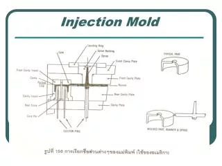
主流道 Sprue 浇口 Gate 产品 Part 分流道 Main Runner 冷料井 Cold Slug Well 次分流道 Branch Runner Filling System Design Typical Filling System
Gate Design • The Number of Gates • Once a gate is added, at least one weld line, one gate mark, more air traps and more runner volume will be added. • As long as the cavity is able to be filled, as expected, gates are the less the better. • In order to reduce the number of gates, each gate shall be located at where the melt is able to cover maximum part area based on the largest melt flow length/thickness ratio .
Ratio of Max. Runner Length /Wall thickness Gate Design L/t t (mm) ABS 160-280 1.5-4.0 PA 200-320 0.8-3.0 PC 100-150 1.5-5.0 PE 200-280 0.3-3.0 PMMA 100-150 1.5-5.0 POM 150-250 1.5-5.0 PP 160-280 0.6-3.0 PVC(Rigid) 100-150 1.5-5.0
Short Side 235 mm Gate Design Even the size and wall thickness are the same, L/t will much different when gate location is different! L (87 mm) L/t will be changed as per the Gate location 132 mm 0.6t 10 mm Gate 35 mm 235 mm L 132 mm 0.6t Long Side Gate 70 mm 165 mm
Gate Design Comparison between 5 Gate and 3 Gate Designs
Gate Design Filling patterns, air-traps and weld lines location needs to be adjusted to less sensitive areas for mechanical strength and cosmetic surfaces
Fan Gate Center Gate Better Worst Worse Best Edge Gate Film Gate Gate Design Gate Design for Flat Part
gate thick gate thick thin thin Poor Good Gate Design Gate Design to Avoid Hesitation Gate location will be the furthest place from hesitation
gate gate Good Poor Gate Design Gate Design to avoid Sink Mark & Void Gate location suggest to be on thick wall gate: 1t Void max. thick.: 6 max. thick.: 6
Poor Good Gate Design Avoid Jetting by Using Impingement Gate Jetting starting at the gate, spreading over the entire molded part Good Poor Jetting Mark
Poor Good Gate Design Avoid Jetting by Profiling Gate Properly Avoid Jetting by using Tab Gate
Gate Design Rectangular Edge Gate Design L = 0.5 ~ 0.75 mm h = n t W When W < 2h, use W= 2h. h =gate thickness (mm)t =wall thickness (mm) W =gate width (mm) A =surface area of cavity (mm2) n =material constant 0.5 for TPU 0.6 for PE, PS 0.7 for POM,PP 0.75 for ABS, SAN, SBC(K-RESIN) 0.8 for PA , PBT, PC, PMMA 0.9 for PPO, PVC, +GF t L h
L= 1.3mm W= w=gate width (mm) A=surface area of cavity (mm2) n=material constant 0.5 for TPU 0.6 for PE, PS 0.7 for POM, PP 0.75 for ABS, SAN, SBC(K-RESIN) 0.8 for CA, PA , PC, PBT, PMMA 0.9 for PPO, PVC, +GF gate thickness (mm)h1 = n t ; h2 = wh1/D t= wall thickness (mm) Gate Design When W < 2h, use W= 2h. Fan Gate Design
Gate Design Pin Gate Design When d < nt, use d = nt d :gate diameter (mm) t :wall thickness (mm) ( (applied to thickness of: 0.75~2.5 mm) C : a function of t, see the table below A : surface area of cavity (mm2) n : material constant 0.5 for TPU 0.6 for PE, PS 0.7 for POM, PP 0.75 for ABS, SAN, SBC(K-RESIN) 0.8 for CA, PA, PBT, PC, PMMA 0.9 for PPO, PVC, +GF L = 0.5 ~ 0.75 mm t d
Dimple d : 4~10 h= 0.75 (t<0.75) =t (0.75≤t≤1.5) =0 (t>1.5) Gate Design
15º ~ 25º 30 ~ Gate Design Sub gate Design h= gate thickness (mm) = nt W= t = wall thickness (mm) W = gate width (mm) A = surface area of cavity (mm2) n = material constant 0.5 for TPU 0.6 for PE, PS 0.7 for POM, PP 0.75 for ABS, SAN, SBC(K-RESIN) 0.8 for PA, PBT, PC, PMMA 0.9 for PPO, PVC, +GF When W < 2h, use W= 2h.
P P P P L L L L R=D/2 10o 2S H 4S D S H S RunnerDesign Hydraulic Diameter DH : hydraulic diameter A : cross-sectional area of the flow P : wetted perimeter
P P P P L L L L R=H/2 S H S S D 10o RunnerDesign Hydraulic Diameter DH : hydraulic diameter A : cross-sectional area of the flow P : wetted perimeter
RunnerDesign Runner Sizing D : runner diameter in mm W : downstream plastic weight L : runner length in mm Note : The above-mentioned empirical formula is suggested as a guide to the size of the runner or branch runner for mouldings weighting up to 200 g, and with wall sections less than 3 mm. For the rigid PVCs and the acrylics, increase the calculated diameter by 25%.
RunnerDesign Runner Sizing
RunnerDesign Runner Sizing 2mm (part thickness) x 1.5 (2.25 if amorphous) = 3.00mm > 2.38mm, so D1=3.00mm
RunnerDesign • Tungsten Steel Ball Cutter (mm)(2Blades) Suggest to use 1.5mm Tungsten steel ball cutter
RunnerDesign Runner Sizing D2is calculated as 4.33mm, Tungsten Steel Ball Cutter (mm)(2Blades radius available: 2mmand2.5mm,Diameter is 4mmand5mm,so suggest to choose R=2.5mm, Tungsten Steel Ball Cutter.
RunnerDesign • Tungsten Steel Ball Cutter (mm)(2Blades) Suggest to use 2.5mm Tungsten steel ball cutter
RunnerDesign PS, ABS W (g) W :weight S : thickness D': reference diameter D’ (mm)
RunnerDesign PE, PP, PA, PC, POM W :weight S : thickness D': reference diameter W (g) D’ (mm)
RunnerDesign L : length of runner fL : correction factor D':reference diameter D: diameter of runner D = D’ x fL
2d secondary runner d Gate primary runner cavity Cold slug well Cold Slug Well Design
RunnerDesign Sprue Bushing Sizing Dave :Average diameter of sprue in mm W :Downstream plastic weight in g L :Sprue length in mm,the shorter the better
Venting System Design Runner Vent Depth: 1. 0.075 mm(easy-flow mat.) 2. 0.125 mm(stiffer-flow mat.) 3. Deep enough to feel flash at runner end Width: - as wide as runner dia. - vent lip: 1.5mm A1(finish) (SPI Finish Designations:A-1 Grade #3 Diamond Buff) vent channel to atmosphere: 1mm(deep)
Venting System Design Parting Line Vent Depth: Check case by case Width: 5mm/25mm orwhole perimeter Length: 1 mm or 1.5 mm A1finish (SPI Finish Designations:A-1 Grade #3 Diamond Buff) Vent channel to atmosphere:1mm deep Injection Vent
Venting System Design Venting Guidelines for fully optimized molds polymer
Cooling System Design Purposes of Mold Cooling Design • 1. Even Cooling (Improve Part Quality) • Efficient Cooling (Increase Productivity) • Thin-wall part can not afford as much thermal induced bending moment as the conventional one does. An even cooling design becomes very important to control the warpage at an acceptable level.
Cooling System Design Injection Molding Cycle Time Fill Time Open Time Post-fill Time
Cooling System Design Typical Cooling System 1 Temperature controlling unit Cooling Circuit 1 Hoses Pump Collection manifold Supply manifold Cooling Circuit 2
Cooling System Design Mold Cooling System
Inlet Outlet Cooling System Design Cooling Channels Outlet Inlet
Cooling System Design Baffle Bubbler
the min. possible cooling time the max. part thickness thermal diffusivity of the melt injection temp. coolant temp. ejection temp. Cooling System Design Min. Possible Cooling Time
Cooling System Design Cooling Time and Thickness Profile Bad Design Good Design
D : Diameter of Cooling Channel, 10 to 14 mm d : Depth, D to 3D P : Pitch, 3D to 5D Cooling System Design Diameter, Depth & Pitch of Cooling Channel
Cooling System Design The cooling rate is not only in proportion of Temperature Difference, but also in proportion of 0.8s of the flow Velocity.
Newton's law of cooling The cooling rate of the cooling body is in proportion to the temperature difference between the substance and the cooling medium Cooling System Design Heat taken from mold by cooling medium Heat transfer coefficient between mold and cooling medium(W/m2-°K) Heat transfer area of cooling channel (M2) Temperature difference between die and cooling medium (degree K) Cooling time (SEC)
Cooling System Design Forced Convention Heat Transfer Inside Tubes and ducts Long Ducts, Liquids and Gases in Turbulent Flow (Re > 6,000, Pr > 0.7) Notes: Re is Reynolds number. Pr is Prandtl number. Nu is Nusselt number. Re, Pr and Nu are all dimensionless.
Heat Transfer Coefficient Cooling System Design
The cooling rate of the mold is not only proportional to the temperature difference between the mold and the water, but also proportional to the 0.8 power of the water flow rate. Cooling System Design Relationship between cooling rate and temperature difference and velocity
Cooling System Design Unbalanced Design