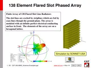
Phased Array Antennas
Phased Array Antennas. Chris Wilson Jarry Ho Eric Szymczak. Introduction. What describes a phased array antenna? Contains many antenna elements Phase and amplitude of each element variable Provides control of the beam direction and pattern shape. Objective.

Phased Array Antennas
E N D
Presentation Transcript
Phased Array Antennas Chris Wilson Jarry Ho Eric Szymczak ENTC 489 RF Dr. Porter
Introduction What describes a phased array antenna? • Contains many antenna elements • Phase and amplitude of each element variable • Provides control of the beam direction and pattern shape ENTC 489 RF Dr. Porter
Objective • Accomplish beam steering electronically, without the mechanical and inertial problems of rotating an entire array ENTC 489 RF Dr. Porter
Applications • Used where rapid target tracking is required • Direction finding • Communications applications where the radiation pattern must be adjusted to accommodate varying traffic conditions ENTC 489 RF Dr. Porter
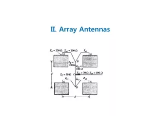
Design Example: 3 element array • λ/2 dipoles • If L1=L2=L3, induced voltages will add in phase • Antennas are seen end-on ENTC 489 RF Dr. Porter
Design Example: 3 element array • Bringing the cables to a common point will make the elements operate as a broadside array • For impedance an match, the cable to the receiver should be 1/3 the impedance of the 3 cables • Or a 3 to 1 impedance transformer can be inserted at the common junction point with all cables of the same impedance ENTC 489 RF Dr. Porter
Design Example: 3 element array • Consider a wave traveling at 45° from the broadside • The in-phase line is parallel to the wave front • L1 ≠ L2 ≠ L3 ENTC 489 RF Dr. Porter
Design Example: 3 element array • If cables of these lengths are joined, the 3 element array will have its beam 45° from broadside ENTC 489 RF Dr. Porter
Design Example: 3 element array • By installing a switch at each antenna element and one at the common feed point and mechanically ganging all switches together, the beam can be shifted from broadside to 45° by operating the ganged switch ENTC 489 RF Dr. Porter
Design Example: 3 element array • By adding more switch points and more cables of appropriate length, the beam can be steered to an arbitrary large number of directions • With more elements, narrower beams can be formed • Controls can be electronic if PIN diodes are used in place of mechanical switches ENTC 489 RF Dr. Porter
Design Example: 3 element array • Instead of controlling the beam by switching cables, a phase shifter can be installed at each element (usually with a ferrite device) • The same effect can also be accomplished by inserting small sections of cable • λ/4, λ/2, and 3λ/4 will provide phase increments of 90°, but smaller increments can be used ENTC 489 RF Dr. Porter
Zero Phase Shift Animation Visuals ENTC 489 RF Dr. Porter
Constant Phase Shift Animation Visuals ENTC 489 RF Dr. Porter
Real World Example • Airborne Warning and Control System (AWACS) • Flown on top of a U.S. military aircraft • Contains an array of 4,000 waveguide slots • Ultra-low side lobes that are below -40 dB • Provides position and tracking information on enemy aircraft and ships, and location and status of friendly aircraft and naval vessels ENTC 489 RF Dr. Porter
AWACS Visuals ENTC 489 RF Dr. Porter
Perspective ENTC 489 RF Dr. Porter
Questions? ENTC 489 RF Dr. Porter
References • Stutzman, W (1988) Antenna Theory and Design, 2nd edn. NY, Wiley and Sons • Kraus, J (1988) Antennas. McGraw-Hill • http://ctd.grc.nasa.gov/5640/Tutorials.html • http://mitglied.lycos.de/radargrundlagen/antennen/ant06-en.html • http://www.fas.org/man/dod-101/sys/ac/e-3.htm ENTC 489 RF Dr. Porter