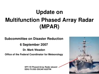
Multifunction Phased Array Radar (MPAR)
Multifunction Phased Array Radar (MPAR). Jeffrey Herd Mark Weber MIT Lincoln Laboratory 20 March 2007. Outline. Introduction to MPAR Concept MPAR Pre-Prototype Development Roadmap Summary. ASR-8. ARSR-1/2. ARSR-3. NEXRAD. TDWR. National Air Surveillance Infrastructure. Future.

Multifunction Phased Array Radar (MPAR)
E N D
Presentation Transcript
Multifunction Phased Array Radar (MPAR) Jeffrey Herd Mark Weber MIT Lincoln Laboratory 20 March 2007
Outline • Introduction to MPAR Concept • MPAR Pre-Prototype • Development Roadmap • Summary
ASR-8 ARSR-1/2 ARSR-3 NEXRAD TDWR National Air Surveillance Infrastructure Future Today ASR-9 ASR-11 ARSR-4 • State-of-the-art active phased array radars • 1 type for all missions: Multifunction Phased Array Radar (MPAR) • Efficient coverage and support infrastructure by eliminating redundancy • Aging mechanically scanned radars • 8 unique types for 4 different missions • Over 500 total with redundant spatial coverage
Concept MPAR Parameters • Active Array (planar, 4 faces) Diameter: 8 m TR elements/face: 20,000 Dual polarization Beamwidth: 0.7 (broadside) 1.0 (@ 45) Gain: > 46 dB • Transmit/Receive Modules Wavelength: 10 cm (2.7–2.9 GHz) Bandwidth/channel: 1 MHz Frequency channels: 3 Pulse length: 1–100 s Peak power/element: 1–10 W • Architecture Overlapped subarray Number of subarrays: 300–400 Maximum concurrent beams: ~160 Aircraft Surveillance Non cooperative target tracking and characterization Weather Surveillance
CONUS Coverage 35% reduction
Preliminary Life Cycle Cost Comparison $2.4B • Assumptions: • 510 legacy @ $5-10M ea • 167 full-size MPAR @ $15M ea • 167 terminal-area MPAR @ $5M ea • Legacy O&M = $0.5M per year • MPAR O&M = $0.3M per year • Replacement of legacy systems with MPAR on as-needed basis saves ~ $2.4B over 20-year period • Majority of savings comes from reduced O&M costs
Tx Peak Power vs. Pulse Compression MPAR Weather Sensitivity • Sensitivity ~ PpNG2t ~ PpN3t • Module cost ~ Pp • Keep Pp small, increase N and lengthen t as needed (with pulse compression for range resolution) • But long t requires short “fill” pulse for close-range coverage: crucial for terminal-area surveillance 1 W / element Compression ratio = 100 TDWR STC On 10 W / element Compression ratio = 10 For 46-dB MPAR antenna gain Pp: Peak power per element N: Number of elements per face G: Antenna gain t: Pulse length
Fill-Pulse and Long-Pulse Sensitivity @ 230 km for long pulse NEXRAD Assumes 46-dB antenna gain -15 dBZ @ end of fill-pulse range > 2W per element with 30 ms long-pulse and 1 ms fill-pulse lengths meets sensitivity requirements ~
Noncooperative Target Surveillance:3D Tracking 300 200 100 Velocity (m/s) 0 100 ATCRBS reply quantization 200 Mode S reply quantization 300 0 10 20 30 40 50 60 70 80 90 Relative Range (m) Height Discrimination Target ID • Current civilian ATC primary radars do not measure target altitude • Cooperative (beacon) response is used • Proposed ADS-B ATC surveillance is entirely cooperative • MPAR could be used for 3D detection/tracking of noncooperative targets, and back up & verification for ADS-B • High PRF and full bandwidth for target characterization • Target ID mode has limited range swath and cannot operate concurrently with other modes • Would be used in brief “point and ID” bursts based on external cues MPAR with monopulse
Outline • Introduction to MPAR Concept • MPAR Pre-Prototype • Development Roadmap • Summary
Notional MPAR Pre-Prototype System = element = brick = subarray center 4544 elements 284 bricks 16 subarrays 8 X 1 beam cluster 4.2 m 16 Subarray Phase Centers 4.2 m Subarray • Pre-Prototype radar demonstrates two simultaneous modes • Aircraft and weather surveillance • Beamwidth: ~ 2º az by 2º el (broadside) • Two independent beam clusters • Electronic steering ±45º az, ±40º el • Up to 8 beams in each 1D cluster • Provides terminal area coverage to @140 km (8 W per element, 20 sec pulse )
MPAR Pre-Prototype Systems Analysis b • Trade off between HPA power, pulse compression ratio, and minimum detectable reflectivity • Desired performance achieved with 8W and 20:1 pulse compression
Multiple Beam Cluster Array Architecture Freq 2 Freq 1 Beam Clusters Switched Dual Pol Radiators LNA LNA LNA HPA HPA HPA Dual-Mode T/R Modules Channelizer Channelizer Channelizer f1 f1 f1 f2 f2 f2 Beamsteering Controller Channelizer Channelizer Channelizer 1 M 2 Analog Beamformer Overlapped Subarray Beamformer 1 N analog Dual Mode Transceivers Digital Receiver Digital Receiver digital Real Time Beamformer Digital Beamformer Radar Signal Processors Back End Processor
‘Brick’ Array Architecture T/R Module Card Modular Brick T/R Modules Standard Eurocard Format • Brick approach provides low cost, scalable architecture • Open frame concept for easy access • Forced air cooling • Chassis modularity • Flexible brick arrangements
Transient Thermal Analysis Physical Geometry Thermal Modelling Transient Response HPA’s Forced Air 85 ° C Temperature, C Time, µsec T/R Card • Transient thermal analysis • 2W, 4W, 8W, 10W peak transmit amplifiers • Varying pulse lengths • Includes critical chip level details • Thermal conductivities of device and interfaces • 8W peak power with 20 µsec pulse is thermally acceptable
Dual Mode T/R Module To Element H-Pol Feed To Element V-Pol Feed Blue = Custom Parts Red = Off the Shelf parts • T/R Module design supports two independent beam clusters • ‘Pick and place’ surface mount parts reduce packaging / assembly costs • Custom RF designs for application-specific components
8W T/R Module Parts Costs v Item Quantity Unit Cost Total Cost HPA 2 $23.00 $46.00 Bias 1 $15.00 $15.00 SP2T 3 $4.00 $12.00 LNA 1 $1.69 $1.69 BPF 1 $3.00 $3.00 Diplx 1 $1.50 $1.50 Vect Mod 3 $2.14 $6.42 Driver 1 $2.50 $2.50 Load 1 $2.00 $2.00 Board 1 $25.00 $25.00 Total = $115.00 • Parts costs driven by HPA chips and PC board fabrication • Packaging / test costs not included • Current HPA chip costs are nearly linear with RF power
T/R Module Components Custom RF Components COTS Evaluation Boards • T/R module utilizes COTS and custom components • Use custom parts only when it reduces cost, or if not available as COTS part LNA Diplexer Vector Modulator Switch (T/R and Pol) HPA Combline Filter Bandpass Filter PC Board
Overlapped Subarray Beamformer RadiatingElement Weighted 1:3 Divider A A A A A 1 2 3 1 2 Weighted 1:4 Combiner Weighted 1:3 Combiner Subarray Output Subarray Output Subarray Output A A A A A A A A A A 1 1 2 2 3 3 1 1 2 2 Overlapped Subarray Architecture Passive Beamformer Layout v • Overlapped subarray enables multiple beam clusters • Tradeoff between analog and digital complexity • Prototype X band overlapped subarray successfully demonstrated under MIT LL IR&D • S band version currently in fabrication
Overlapped Subarray Beamformer on RFIC Chip RFIC CMOS Beamformer Chip Measured RFIC Beamformer Pattern Ideal Measured 12 Element X band Subarray • RFIC beamformer reduces cost, size and weight • Programmable weights enable optimized beam patterns and advanced calibration • Prototype X band RFIC demonstrated under MIT LL IR&D
Dual Mode Receiver Dual Mode Receiver Architecture Bench Test Dual Mode Receiver v • Parts evaluation confirms discreet component performance • SFDR = 70 dB, NF = 5.3 dB, OIP3=34 dBm • Parts costs = $225 • EMI modeling and testing of surface mount boards is critical
Digital Subarray Beamformer Digital Beamformer Architecture 8 Digital Beam Cluster v • Processing simulation tool developed for Pre-Prototype MPAR • Identified critical kernels • 16 channel FPGA testbed to test and evaluate kernel designs
Preliminary Parts Cost Estimates Equivalent Cost per Element - Parts Only Totals: $455.75 $153.50 * Assumes 8W module incl RF board with sequential polarization ** Assumes 2W module incl RF board with sequential polarization *** Assumes standard beamformer in azimuth **** Assumes hybrid tile/brick architecture
Outline • Introduction to MPAR Concept • MPAR Pre-Prototype • Development Roadmap • Summary
Notional MPAR Pre-Prototype Development Schedule Year 1 Year 2 Year 3 Year 4 PDR Testing CDR CDR Concept Development, Design, and Subsystem Prototyping System Fabrication and Assembly Experimental Testing and Evaluation Brick Subarray Data Collection Array • 80 Element Subarray • Digital Beamformer DBF) • Algorithm Dev • System Simulation • 4544 Element Array • 16 Channel DBF • System Simulation • Test Planning • Collect Multimode Data • Process Data • Report Results • 16 Element Brick • Transceiver • Waveform Design • Systems Analysis Analog and Digital Hardware: Systems Analysis & Signal Processing:
Summary • Key MPAR features • Lower O&M costs • Scalable • Multifrequency • Dual polarization • Digital beamforming (multiple receive beam clusters) • Adaptive control • Low module peak power • Auxiliary mode functions • MPAR Pre-Prototype Technology Demonstration Program • Shows path to ultra-low cost implementations • Provides a means to develop and test MPAR concept • Solidifies key technical requirements • Critical demos provide early performance and cost data • Dual mode T/R module • Overlapped subarray beamformer • Dual mode receiver • Digital beamformer • Thermal management