Download
1 / 34
410 likes | 778 Vues
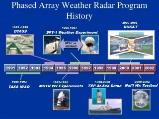
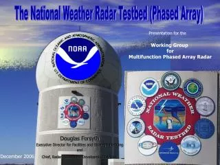
The National Weather Radar Testbed (Phased Array). Presentation for the. Working Group for Multifunction Phased Array Radar. Douglas Forsyth Executive Director for Facilities and Strategic Planning and Chief, Radar Research & Development Division. December 2006. Outline. Background

E N D
The National Weather Radar Testbed (Phased Array) Presentation for the Working Group for Multifunction Phased Array Radar Douglas Forsyth Executive Director for Facilities and Strategic Planning and Chief, Radar Research & Development Division December 2006
Outline • Background • Funding History • System Overview • Data Quality • Upgrades Completed • 1st Tornadic Data Set • Future Upgrades
Collaborators James Kimpel Dusan Zrnic Ron Ferek Tom McNellis Richard Vogt Jerry Crain Alan Shapiro William Benner John Heimmer
Behind the Scenes Allen Zahrai, Dick Doviak, Mike Schmidt and Richard Wahkinney Bob Staples, John Carter, Igor Ivic Roger Simer, Brian Frasco, Sheldon Katz, Tim Maese, Ann Wiser, Steven Silberstein, Wayne Sabin, Mark Campbell Russell Cook Richard Vogt Susan Sedwick, John Havlicek Nannette Kalani, Jim Olivo Jim Melody, Les Lemon, Bob Blasewitz
More Behind the Scenes Mark Benner, Mike Schmidt, Richard Wahkinney, Kurt Hondl, Allen Zahrai. Bob Staples, Chris Curtis, Rick Adams, John Thompson, Dave Priegnitz, Dan Suppes Mark Campbell, Tim Maese, Wayne Sabin, Tim Hughes, John Petree B. Ballard Susan Sedwick Nannette Kalani Jim Melody, Paul Baumgarder, Bob Blasewitz, Tim Maese
Additional Collaborators Qin Xu, Mike Jain Pam Heinselman, Sebastian Torres Bob Palmer, Tian-You Yu, Mark Yeary, Phil Chilson, Guifu Zhang Gary Mitchell
HISTORY • NSSL Advance - 1997 • Desire to build a phased-array radar for weather applications • Visit by Lockheed-Martin - 1998 • Established collaborations with Office of Naval Research, Lockheed-Martin, and University of Oklahoma - 1999 • Added additional partners, NWS Radar Operations Center, FAA, NOAA, Oklahoma State Regents for Higher Education, Basic Commerce Industries
Phased Array Radar Support FY2000 - 2003 • U.S. Navy ($10M), SPY-1 antenna ($10M) • NOAA/NWS - WSR-88D transmitter ($0.4M) • NOAA/OAR ($1.0M, EP) • Lockheed Martin ($1.0M in kind, EP) • Oklahoma State Regents ($1.0M, EP) • U. of Oklahoma ($0.5M, EP) • FAA ($8.0M) • Navy/NOAA/FAA MOU 2004 2005 2006 2007 NOAA $1M $1M $4M $3M? FAA (to NOAA) $.8M $.8M $0M
What is Phased Array? • Phasing = Timing • Analogous: Ears & Sound waves • Array of many Elements • 4-sided, no moving parts, scanned Electronically vs. mechanically (WSR-88D) • Results: Faster Scans, more flexible scans
Phased Array Radar (PAR) One Beam Multi-Beam
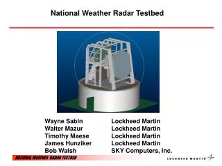
NWRT Equipment AN/SPY-1A Position Programmer (APP) AN/SPY-1A Antenna Environmental Processor (EP) WSR-88D Transmitter Pedestal & Antenna Pedestal Control (APC) Real-Time Controller (RTC) Receiver/Exciter Testbed Control Center (TCC) Radome Facility
Passive Array Min PRI = 800 msec Short Pulse = 1.57 msec Long Pulse = 4.71 msec Sensitivity = 5.89 db at 50 km Wavelength = 9.375 cm
Phased Array Antenna Beam width (Center) = 1.5 deg Beam width (+/- 45 deg) = 2.1 deg Antenna Tilt = 10 deg Antenna Height = 40 ft Element Module 136 modules 32 elements per module 4,352 elements
RAID Development System Removable Hard Drive Operational System Environmental Processor (EP) • SkyComputers • Ultra SPARC – Host • 5 SKYbolt II modules each with 4 PowerPC G4 processors • CD, hard and removable hard drive • Ciprico RAID 648 Gbyte storage • Development System – 2 SKYbolt II modules
Matrix PC replacing the Environmental Processor (EP) • Matrix PC • Six Supermicro PCs • Dual Intel Xeon 2.4Ghz • 2GB memory • Linux OS • Connected to RTC via Systran SL100 PCI Card • Myrnet Crossbar Switch • Direct PC to PC communication at 2 Ghz • 3 TB Raid • 24 Port Network Switch • One Node currently used to replace existing EP
Multi-use Aircraft Tracking • FAA and BCI development • Uses Separate Processor for Data stream • Runs simulateously with Weather Data collection
KTLX 0.5 deg NWRT 0.75 deg 2003/11/04 2123 UTC (Refl)
2003/11/04 2123 UTC (Vel) KTLX 0.5 deg NWRT 0.75 deg
NWRT STATUS • Data Quality Issues Corrected • Bad Velocities • Digital receiver filters • Clear Mode • Pulse Timing • Six Degree Phase error • Engineering Testing Phase Completed • Fixed STIM download problems
Upgrades Completed • Backup Generators – Radar Facility and TCC • Continuous rotation 18 degrees per second • Volume scan (14 levels) less than 60 seconds • Improved display system • Improved User Interface
Current Work • Continue to learn operational capabilities (i.e. scan strategies, various processing modes, etc.) • Collect data for comparisons with WSR-88D and TDWR during storm season • Use for various Research Projects • Transverse winds (NSSL/OU) • Refractive Index (OU) • Spectral Signatures of Tornadoes (OU/NSSL) • Clutter Canceling (NSSL/OU) • Scan Strategies – Beam Multiplexing (NSSL/OU)
Current Work • Add Remote Operations (completed, fine tuning) • Replace EP (completed, along with I/Q recording) • Integrate with WDSS-II algorithms and 3-D displays • Test Multi-use (FAA/BCI – aircraft tracking) • Testing beam multiplexing • Measure Antenna pattern • Emulate adaptive Volume scans • Start design of dual-polarized sub-array
Beam Multiplexing Beam Multiplex Difference VCP 12
May 29th ComparisonGridded • Diff Times/Accuracy • Different Radar Locations • Ground Clutter • 2nd Trip • Polarization • Resolutions 1km vs. 244m • Sensitivity • Calibration errors • Beam Widths • Elevation Angle • PRT (Dwells)
Research Agenda (1-2 years) • Learn Operational capabilities (I.e. scan strategies, various processing modes, etc.) • Collect data for comparisons with WSR-88D and TDWR during storm season • Use for various Research Projects • Add Remote Operations (completed, fine tuning) • Replace EP • Integrate with WDSS-II algorithms and 3-D displays • Test Multi-use (FAA – aircraft tracking) • Implement beam multiplexing • Start design of dual-polarized sub-array
Future Plans • Available as National Facility in December 2006 • Adaptive scanning • Continue to test Multi-use applications • Wind profiling • Aircraft tracking • Chemical/Biological profiling • Initialization of Models
WSR-15PWA Locations Dual Polarization ROADMAP 2025 2004 2007 2012 2015
THANK YOU http://www.nssl.noaa.gov
VCP -12 • Elevation Angles • 0.5 • 0.9 • 1.3 • 1.8 • 2.4 • 3.1 • 4.0 • 5.1 • 6.4 • 8.0 • 10.0 • 12.5 • 15.6 • 19.5 The lowest three angles use "Split Cut" (CS/CD), middle angles use Batch (B), and higher angles use Contiguous Doppler (CDX) mode.