Download
1 / 21
360 likes | 1.02k Vues
Development of Active Phased Array Weather Radar. Masakazu Wada. Comparison of Dual-Pol and Phased-array Radar. Parabolic radar. Phased Array Weather Radar. Concept on Phased-array Radar. About 2m. About 2m. Overview of Antenna. Overview of Antenna Scan. < Cost Performance >

E N D
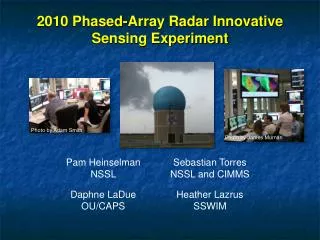
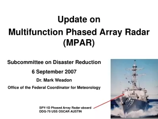
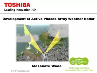
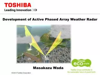
Development of Active Phased Array Weather Radar Masakazu Wada
Comparison of Dual-Pol and Phased-array Radar Parabolic radar Phased Array Weather Radar Development of Active Phased Array Weather Radar
Concept on Phased-array Radar About 2m About 2m Overview of Antenna Overview of Antenna Scan • <Cost Performance> • 1-dimension Active Phased Array Antenna and DBF(Digital Beam Forming) • Maximize the Cost Performance • The same price range as compared to parabolic radar • <Antenna Scan> • 1 degree of azimuth beam width by slotted antenna mechanically • 1 degree of elevation beam width by Antenna electronically • Fan beam transmission • Multi-beams receiving by DBF • 3D fast observation with one rotation Development of Active Phased Array Weather Radar
Block Diagram DBF A/D and I/Q(128 lines) Receiver(96 lines) Rx Frequency Conversion(128 lines) DBF output (16 beams) • Digital Signal Processor • Pulse Compression • Calculate • Radar Reflectivity • Doppler Velocity Velocity Width Slotted Waveguide antenna (128 elements) ………… ………… …………….. …………….. No DBF output (128 I/Q data) I/Q Data Accumulation (for study) Transmitter and Receiver(24 lines) .. … … Tx Frequency Conversion ~ D/A Digital Seed Use Gallium Nitride on Tx Amp Development of Active Phased Array Weather Radar
Active Phased Array Antenna 2.1m 2.2m Active Phased Array Antenna Development of Active Phased Array Weather Radar
Tx/Rx Unit Condenser card Tx/RxCard FrequencyConversionCard Include 8ch Tx/Rx Elements The system uses 3 units Development of Active Phased Array Weather Radar
Receiving Unit RxCard FrequencyConversionCard Include 8ch Rx Elements The system uses 13 units Development of Active Phased Array Weather Radar
Frequency Conversion Card Development of Active Phased Array Weather Radar
A/D I/Q Unit 16ch A/D & I/Q The system uses 8 units Development of Active Phased Array Weather Radar
DBF Unit The system uses DBF technique to calculate beam form from 128 I/Q data Development of Active Phased Array Weather Radar
Observation Mode Prepare wide observation mode and fast obsevation mode Development of Active Phased Array Weather Radar
Phased-array Radar installed in Osaka Univ. Active Phased Array Antenna Left: Radar Processor Right: Radar Controller Active Phased Array Weather Radar installed in Osaka Univ. Development of Active Phased Array Weather Radar
Conclusion • Active Phased-array Weather Radaris able to generate 3D data without any gap in the period of 10 to 30seconds, in order to capture cumulonimbus quickly. • We have installed Active Phased-array Radar on Osaka urban areaand are evaluating it now. • To protect safety of critically significant infrastructure such as urban area and Airport from disaster, Toshiba propose multiple observation using dual-pol solid-state radar and 1D phased-array radar. This research is supported by the National Institute of Information and Communications Technology, Japan. Development of Active Phased Array Weather Radar
Toshiba’s Presentations in the Exhibition • Exhibitor Booth <No. 5005> Right in front of main entrance
Measurement ( Anechoic Chamber ) We have one of the largest Chamber in Eastern Japan. Development of Active Phased Array Weather Radar
NSI Receiver Amplitude Phase Near field data Azimuth Elevation Calculated far field pattern Development of Active Phased Array Weather Radar
Antenna Pattern ( Azimuth) <Beam Width>1degree or less <Side lobe> -23dB or less Mechanical Beam Forming by Slot Antenna Development of Active Phased Array Weather Radar
Transmission and Receiving Pattern ( Elevation) <Beam Width>1degree (Rx) <Side lobe> -10dB or less (Tx) -23dB or less (Rx) 1 transmission beam and receiving multi beam by DBF Electronic Scan EL 0deg to 90 deg Development of Active Phased Array Weather Radar
Forecast of potential Maturation Decline stage Developing stage Forcast at this Strong rainfall Life cycle of Cumulonimbus Vertical Integrated Liquid (VIL) and by the vertical distribution of precipitation, it is possible to predict the precipitation may fall to the ground in the near future
Transmitted Waveform Solid-state Pulse Compression Radar Klystron Amplifier Delay time time t Frequency Pulse Compression Technique • Transmission power can be reduced compared with conventional radar systems on a detection-range basis. • >> Reduction in operating voltage of the transmitter circuits • >> Downsizing of the transmitter • >> Suppression of the level of interference wave, etc. Peak power can be minimized without lowering the average power • Chirp modulation ( Frequency modulation ) • 1) add the frequency modulation on the transmission pulse 2) transmit this linear FM pulse 3) put the received signal through the time delay filter 4) collect the divided frequency power in the received pulse • 1) 2) 3) 4) Development of Active Phased Array Weather Radar