K15/21/25 Gasoline Engine
640 likes | 880 Vues
K15/21/25 Gasoline Engine. Service Manual # 99789-75100.

K15/21/25 Gasoline Engine
E N D
Presentation Transcript
K15/21/25 Gasoline Engine Service Manual # 99789-75100
The following modules do not cover all of the material in the manual. We have identified and chosen some of the more important key points. To fully understand the engine in more depth you will need to read the manual. More hands on work with the lift truck, and real life work will improve your overall knowledge of this equipment.
Cylinder Head Cylinder head is common with K15, k21and K25 Made of aluminum alloy material
Rocker Cover Removal of rocker cover and gasket: 1. Remove the rocker cover retaining nuts. 2. Remove rocker cover.
Rocker Shaft Assembly • Removal of rocker shaft assembly. • Loosen the eight valve rocket adjusting nuts and screws to remove the valve rocker shaft. • Pull off the push rod. • When removing the valve rocker shaft, compress the coil spring slightly and tie the spring with a metal wire, as shown in the figure, before loosening the bolts. This will facilitate the reassembly work later.
Assemble Cylinder Head • Retighten the bolts in the sequence shown in the figure while the engine is cold. • Torque: 68.6 N-m (7.0kgf·m)
Assemble Rocker Shaft Assembly Tighten the rocker shaft retaining bolts evenly from inside to outside Torque: 17.64 – 21.56 N-m (1.8 – 2.2kgf·m)
Adjusting Valve Clearance • 1. Start the engine and fully warm it up. Then stop engine. • 2. Remove rocker cover • 3. Turn crankshaft – Set piston for No. 1 cylinder to the compression TDC and adjust valve clearance for (1) (2) (3) (5) in step 1. • 4. Set piston fro No. 4 cylinder to the compression TDC and adjust valve clearance for (4) (6) (7) (8) in step 2. Adjust Valve Clearance when Engine is Hot
Adjusting Valve Clearance Intake and Exhaust: 0.38 mm Adjust Valve Clearance when Engine is Hot
Piston And Connecting Rod • The front of the connecting rod is determined as follow: • When installed to the piston and view from the front, the projection should come to the right.
Assembly of Piston Ring • 1. Securely assemble the top ring, second ring and oil ring to their relevant positions. • 2. Make sure to assemble these parts in the following order: oil ring, second ring, top ring.
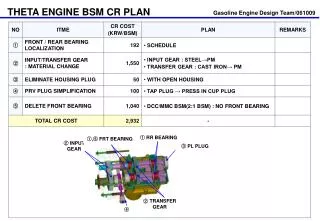
Assembly of Camshaft 1. Gently put the camshaft into the camshaft hole so that the bearing bushings are no damaged. 2. Tighten locating plate to the specified torque. 8.43 – 10.8 Nm (0.86 – 1.1 kgf.m)
Assembly of Timing chain/Sprocket Tighten camshaft bolts. Tightening torque: 39.2 – 49 Nm (4.0 – 5.0 kgf.m)
Assembly of Timing chain/Sprocket Check the height of the cam shaft gear and crankshaft gear end faces, adjust the height by adding shims to the crankshaft side as necessary.
Assembly of Timing chain/Sprocket Assemble chain tensioner. When installing the chain tensioner, align the oil holes of the tensioner body to those of the cylinder block to ensure that the tensioner spindle shoe (synthetic rubber) is held parallel with the chain. CAUTION: Assemble shoe correctly
Installation of Crankshaft Pulley Set the crankshaft pulley by aligning the pulley claws to the groove of the bushing.
Remove Water Pump 1. Open the drain of the radiator and extract coolant. 2. Remove the radiator shroud. 3. Loosen the alternator adjusting bolt. 4. Fully put aside the alternator toward the engine. 5. Remove fan and fan pulley 6. Remove water pump together with the gasket.
Water Pump Inspection Check the water pump vanes for rust and pitching. Do not disassemble water pump
Water Pump Inspection Check the water pump bearing for proper end play and smooth operation. Do not disassemble water pump
Fan Belt Tension Belt Deflection: 11 – 13 mm Force: 98 N (10 kgf)
Fuel Pump & Fuel Filter Periodically inspect, clean and replace fuel filter. Clean fuel filter every 3 months.
Spark Plug Gap Standard (mm) : 9