Timer 0
Timer 0. Introduction. The Timer0 module has the following features: 8-bit timer/counter Readable and writable 8-bit software programmable prescaler Clock source selectable to be external or internal Interrupt on overflow from FFh to 00h Edge select for external clock.


Timer 0
E N D
Presentation Transcript
Introduction • The Timer0 module has the following features: • 8-bit timer/counter • Readable and writable • 8-bit software programmable prescaler • Clock source selectable to be external or internal • Interrupt on overflow from FFh to 00h • Edge select for external clock
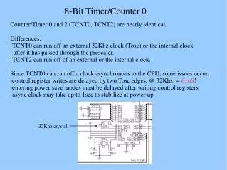
Operation • Timer mode is selected by clearing the T0CS bit (OPTION<5>). • Counter mode is selected by setting the T0CS bit (OPTION<5>). • In counter mode, Timer0 will increment either on every rising or falling edge of the T0CKI pin. • Clearing the T0SE bit selects the rising edge. • The prescaler is mutually exclusively shared between the Timer0 module and the Watchdog • Timer. The prescaler assignment is controlled in software by the PSA control bit (OPTION<3>).
TMR0 timing • Any write to the TMR0 register will cause a 2 instruction cycle (2TCY) inhibit. That is, after the TMR0 register has been written with the new value, TMR0 will not be incremented until the third instruction cycle later. • When the prescaler is assigned to the Timer0 module, any write to the TMR0 register will immediately update the TMR0 register and clear the prescaler.
TMR0 Interrupt • The TMR0 interrupt is generated when the TMR0 register overflows from FFh to 00h. • This overflow sets bit T0IF (INTCON<2>). The interrupt can be masked by clearing bit T0IE (INTCON<5>).
TMR0 Prescaler • An 8-bit counter is available as a prescaler for the Timer0 module, or as a postscaler for the Watchdog Timer • When assigned to the Timer0 module, all instructions writing to the TMR0 register (e.g., CLRF TMR0, MOVWF TMR0, BSF TMR0,x....etc.) will clear the prescaler. • When assigned to WDT, a CLRWDT instruction will clear the prescaler along with the Watchdog Timer. • The prescaler is not readable or writable.
TMR0 initialization • CLRF TMR0 ; Clear Timer0 register • CLRF INTCON ; Disable interrupts and clear T0IF • BSF STATUS, RP0 ; Bank1 • MOVLW 0xC3 ; PortB pull-ups are disabled, • MOVWF OPTION_REG ; Interrupt on rising edge of RB0 • ; Timer0 increment from internal clock • ; with a prescaler of 1:16. • BCF STATUS, RP0 ; Bank0 • BSF INTCON, T0IE ; Enable TMR0 interrupt • BSF INTCON, GIE ; Enable all interrupts • END • ‘OR’ • ; If TMR0 interrupt is disabled, do polling on the overflow bit • ; • T0_OVFL_WAIT • BTFSS INTCON, T0IF • GOTO T0_OVFL_WAIT • ; Timer has overflowed