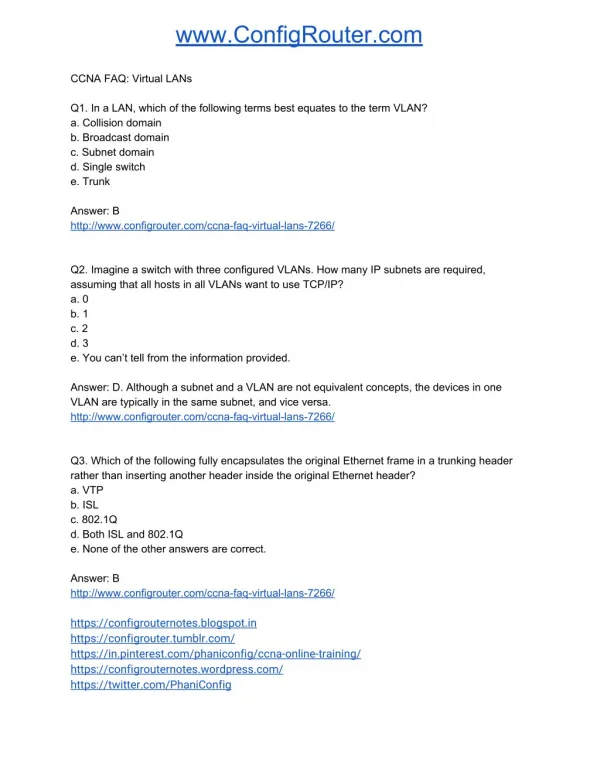
CCNA 3 v3.0 Module 8 Virtual LANs
300 likes | 665 Vues
CCNA 3 v3.0 Module 8 Virtual LANs. Cisco Networking Academy. Objectives. VLAN concepts VLAN configuration Troubleshooting VLANs. Benefits of VLANs. Easily move workstations on the LAN Easily add workstations to the LAN Easily change the LAN configuration

CCNA 3 v3.0 Module 8 Virtual LANs
E N D
Presentation Transcript
CCNA 3 v3.0 Module 8 Virtual LANs Cisco Networking Academy
Objectives • VLAN concepts • VLAN configuration • Troubleshooting VLANs
Benefits of VLANs • Easily move workstations on the LAN • Easily add workstations to the LAN • Easily change the LAN configuration • Easily control network broadcast traffic • Improve security
VLANs VLANs logically segment switched networks based on an organization's functions, project teams, or applications as opposed to onlya physical or geographical basis. However, geographic VLANs (local VLANs) are becoming more common.
Local VLANs • VLANs are more frequently being created around geographic boundaries (wiring closet) rather than commonality (application) boundaries. • traffic flow patterns utilize the new 20/80 rule • the user must cross a Layer 3 device in order to reach 80 percent of the resources • considerably easier to manage and conceptualize than VLANs that span different geographic areas
In this example, 3 different FastEthernet interfaces are being used. However, subinterfaces can be created instead to achieve the same design goal. Router(config)# int fa0/0.1 Router(config)# int fa0/0.2 Router(config)# int fa0/0.3 One physical interface Example with 1 Switch, 3 VLANs and 3 Broadcast Domains
VLAN Configuration VLANs can be configured as static or dynamic. • Statically: • Network administrators configure port-by-port • Each port is associated with a specific VLAN • Network admin. is responsible for keying in the mappings between the switchports and VLANs • Dynamically: • Switchports are able to dynamically configure their VLAN association • Uses a software database of MAC addresses to VLAN mappings (which the network admin. must set up first)
Dynamic VLANs • With a VLAN Management Policy Server (VMPS), you can assign switch ports to VLANs dynamically. • When you enable VMPS, a MAC address-to-VLAN mapping database downloads from a Trivial File Transfer Protocol (TFTP) server and VMPS begins to accept client requests. • Note: The VLAN Trunking Protocol (VTP) management domain and the management VLAN of VMPS clients and the VMPS server must be the same.
VLAN Types • Port Based: • Most common configuration method • Ports assigned individually, in groups or across multiple switches • Simple to use/administer • MAC address: • Rarely implemented today • Each address must be entered into the switch and configured individually • More administrative overhead
Communicating Between VLANs One physical interface
Interswitch Communication and VTP • In order for switches to communicate between each other, a trunk link must be established from switch to switch using a trunking protocol. • Trunk links carry frames from all VLANs. • Trunking ports tag frames with a VLAN ID before the frame is forwarded to another switch. • The VLAN tag is then removed before the frame is forwarded out an access port.
Access/Trunk Links ISL or 802.1q • An access link is a link on the switch that is a member of only one VLAN. • referred to as the native VLAN of the port • A trunk link is capable of supporting multiple VLANs. • typically used to connect switches to other switches or routers
VLAN Trunking Protocols • The switch has two methods of identifying the VLAN that a frame belongs to when the switch receives the frame on a trunk link. • Cisco proprietary ISL standard • IEEE 802.1Q standard • There are other trunking encapsulation types but we will focus on these two.
VLAN Frame Identification http://www.cisco.com/en/US/tech/tk389/tk390/technologies_tech_note09186a0080094665.shtml
VLAN Trunking Protocol • A VTP domain is made up of one or more interconnected devices that share the same VTP domain name. • A switch can be configured to be in one VTP domain only. • Global VLAN information is propagated across the network by way of connected switch trunk ports. • When transmitting VTP messages to other switches in the network, the VTP message is encapsulated in a trunking protocol frame such as ISL or IEEE 802.1Q. • In order to share VTP information, switches must be in the same VTP domain.
Users are grouped into VLANs independent of physical location, but dependent on group or job function. All users in a VLAN should have the same 80/20 traffic flow patterns. As a user moves around the campus, VLAN membership for that user should not change. Each VLAN has a common set of security requirements for all members End-to-End VLANs
VLAN Configuration The following guidelines must be followed when configuring VLANs on Cisco 29xx switches: • The maximum number of VLANs is switch dependent. • VLAN 1 is one of the factory-default VLANs. • VLAN 1 is the default Ethernet VLAN. • Cisco Discovery Protocol (CDP) and VLAN Trunking Protocol (VTP) advertisements are sent on VLAN 1. • The Catalyst 29xx IP address is in the VLAN 1 broadcast domain by default. • The switch must be in VTP server mode to create, add, or delete VLANs.
Creating and Deleting VLANs To Create VLANs: Switch# vlan database Switch(vlan)# vlan 2 Switch(vlan)# vlan 3 name Accounting Switch(vlan)# no vlan 4 To group a switchport to a VLAN: Switch(config)# int range fa0/1 - 4 Switch(config-range-if)# switchport mode access Switch(config-range-if)# switchport access vlan 2 Switch(config-range-if)# no switchport access vlan 2 Switch(config-range-if)# int g0/1 Switch(config-if)# switchport mode trunk 2900XL: Switch(config-if)# switchport mode trunk Switch(config-if)# switchport encapsulation isl | dot1q The Catalyst 2900XL will do both ISL and 802.1q encapsulation so you must specify at the switchport.
Common Problems in Troubleshooting VLANs • Ports grouped to incorrect VLAN • Trunk link between switches may not have the same encapsulation on both sides • VTP Domain name different • Duplex and speed mismatch • Intervlan routing configured incorrectly at router
VLAN Troubleshooting Scenarios A trunk link cannot be established between a switch and a router
VLAN Troubleshooting Scenarios VTP is not properly propagating VLAN configuration changes between switches.