Download
1 / 35
350 likes | 377 Vues
Learn the fundamentals of finite element analysis for virtual engineering. Explore modeling concepts, mesh generation, load placement, and more in lectures and labs.

E N D
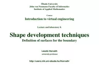
Óbuda University John von Neumann Faculty of Informatics Institute of Applied Mathematics CourseIntroduction to virtual engineering Lecture and laboratory 6. Finite element mesh and load definition László Horváth university professor http://users.nik.uni-obuda.hu/lhorvath/
Contents Lecture Concept of finite element analysis Completing part models for finite element analysis Finite elements and placing loads for analysis Concept of associative, parametric, and adaptive mesh Laboratory Introduction by studying typical FEA tasks (VE6.1/a-b) Creating and studying finite element mesh on a spatial surface (VE6.2) LászlóHorváth ÓU-IAM http://users.nik.uni-obuda.hu/lhorvath/
Concept of finite element analysis Calculation of parameters on nodes in a mesh Node Edge Approximation of location dependent parameters as design variables acting on the design performance on a finite number of finite elements Finite Element Modeling (FEM) creates extended part and assembly model forFinite Element Analysis (FEA) A numerical method LászlóHorváth ÓU-IAM http://users.nik.uni-obuda.hu/lhorvath/
Completing part models for finite element analysis(preprocessing) Preparation of FEM Preparation of geometric Definition of loads and model Mesh generation boundary conditions Hálógenerálás Controlled by engineer Convert model from outside source Automatic Selection of material properties New geometric model Automatic correction Checking for consistency Simplified regions Refining mesh and correctness New entities Optimizing mesh LászlóHorváth ÓU-IAM http://users.nik.uni-obuda.hu/lhorvath/
Finite elements and placing loads for analysis One-dimensional Planar Shell Solid Mesh Elements LászlóHorváth ÓU-IAM http://users.nik.uni-obuda.hu/lhorvath/
Finite elements modeling This FEM/FEA modeling and analysis are done as Laboratory task VE6.1/a. Part modeling is included in .ppt for lecture 8. LászlóHorváth ÓU-IAM http://users.nik.uni-obuda.hu/lhorvath/
Finite elements modeling LászlóHorváth ÓU-IAM http://users.nik.uni-obuda.hu/lhorvath/
Finite elements and placing loads for analysis Several frequently applied loads Concentrated and distributed force. Torque. Contact pressure. Acceleration (gravity, translation, rotation). Temperature on surface. Concentrated or distributed heat source. Magnetic. Placing loads and restraints Making simulation of real operating conditions possible. On mesh (at nodes). On geometry of the part (along lines and on surfaces). Mathematical expressions. Automatic contact recognition. Boundary conditions Mechanical restraints restrict movements in specified directions and result reaction forces. Definition of degrees of freedom. Non-restrained nodes have six degrees of freedom. LászlóHorváth ÓU-IAM http://users.nik.uni-obuda.hu/lhorvath/
Placing clamp restraint (DOF=0) on geometry LászlóHorváth ÓU-IAM http://users.nik.uni-obuda.hu/lhorvath/
Placing bearing load on geometry LászlóHorváth ÓU-IAM http://users.nik.uni-obuda.hu/lhorvath/
Placing distributed force load on geometry LászlóHorváth ÓU-IAM http://users.nik.uni-obuda.hu/lhorvath/
Compute the model LászlóHorváth ÓU-IAM http://users.nik.uni-obuda.hu/lhorvath/
Compute the model LászlóHorváth ÓU-IAM http://users.nik.uni-obuda.hu/lhorvath/
Concept of associative, parametric, and adaptive mesh Two-way associative connection between shape model and mesh for automatic change of the mesh in case of changed geometry. Mesh is characterized by parameters mainly for the definition of its dimensions. Adaptive mesh definition is an automatic modification of mesh density, element order, and element shape. Density can vary according to the load on each region. LászlóHorváth ÓU-IAM http://users.nik.uni-obuda.hu/lhorvath/
Visualize the mesh LászlóHorváth ÓU-IAM http://users.nik.uni-obuda.hu/lhorvath/
Definition of solution and visualize color ranges LászlóHorváth ÓU-IAM http://users.nik.uni-obuda.hu/lhorvath/
Visualize with and without deformation LászlóHorváth ÓU-IAM http://users.nik.uni-obuda.hu/lhorvath/
Nodal values – details from different regions of the solid LászlóHorváth ÓU-IAM http://users.nik.uni-obuda.hu/lhorvath/
Finite element modeling and analysis Laboratory task VE6.1/b. LászlóHorváth ÓU-IAM http://users.nik.uni-obuda.hu/lhorvath/
Definition of a mechanical part to be analyzed Slides 8-13 show main steps of the part definition. If you can not understand the definition process, please refer to relevant slide shows for the previous lectures or to the lecturer. Laboratory task VE6.2 includes definition of this part. LászlóHorváth ÓU-IAM http://users.nik.uni-obuda.hu/lhorvath/
Definition of a mechanical part to be analyzed LászlóHorváth ÓU-IAM http://users.nik.uni-obuda.hu/lhorvath/
Definition of a mechanical part to be analyzed LászlóHorváth ÓU-IAM http://users.nik.uni-obuda.hu/lhorvath/
Definition of a mechanical part to be analyzed LászlóHorváth ÓU-IAM http://users.nik.uni-obuda.hu/lhorvath/
Definition of a mechanical part to be analyzed LászlóHorváth ÓU-IAM http://users.nik.uni-obuda.hu/lhorvath/
Definition of a mechanical part to be analyzed LászlóHorváth ÓU-IAM http://users.nik.uni-obuda.hu/lhorvath/
Definition of load and restraint in Finite Element Model (FEM) Laboratory task VE6.1/b includes definition of the subsequent FEM and FEA model. LászlóHorváth ÓU-IAM http://users.nik.uni-obuda.hu/lhorvath/
Visualization of mesh in Finite Element Model (FEM) LászlóHorváth ÓU-IAM http://users.nik.uni-obuda.hu/lhorvath/
Finite Element Analysis (FEM) LászlóHorváth ÓU-IAM http://users.nik.uni-obuda.hu/lhorvath/
Introduction by studying typical FEA tasks Source: www.catia.com LászlóHorváth ÓU-IAM http://users.nik.uni-obuda.hu/lhorvath/
Introduction by studying typical FEA tasks Source: www.catia.com LászlóHorváth ÓU-IAM http://users.nik.uni-obuda.hu/lhorvath/
Creating and studying finite element mesh on a spatial surface Laboratory task VE6.2 LászlóHorváth ÓU-IAM http://users.nik.uni-obuda.hu/lhorvath/
Creating and studying finite element mesh on a spatial surface LászlóHorváth ÓU-IAM http://users.nik.uni-obuda.hu/lhorvath/
Creating and studying finite element mesh on a spatial surface LászlóHorváth ÓU-IAM http://users.nik.uni-obuda.hu/lhorvath/
Creating and studying finite element mesh on a spatial surface LászlóHorváth ÓU-IAM http://users.nik.uni-obuda.hu/lhorvath/
Creating and studying finite element mesh on a spatial surface LászlóHorváth ÓU-IAM http://users.nik.uni-obuda.hu/lhorvath/