Synchronous Versus Asynchronous Testing
Synchronous Versus Asynchronous Testing. Vishwani D. Agrawal James J. Danaher Professor Electrical and Computer Engineering Auburn University, Auburn, AL 36849, USA Collaborator: Praveen Venkataramani Texas Instruments – Bangalore, July 11, 2012. Power Considerations in Design.

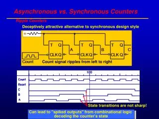
Synchronous Versus Asynchronous Testing
E N D
Presentation Transcript
Synchronous Versus Asynchronous Testing Vishwani D. Agrawal James J. Danaher Professor Electrical and Computer Engineering Auburn University, Auburn, AL 36849, USA Collaborator: Praveen Venkataramani Texas Instruments – Bangalore, July 11, 2012 Agrawal: Synch. vs. Asynch.
Power Considerations in Design • A circuit is designed for certain function. Its design must allow the power consumption necessary to execute that function. • Low power design methods can reduce the power need. • Power buses are laid out to carry the maximum current necessary for the function. • Heat dissipation of package conforms to the average power consumption during the intended function. • Layout design and verification must account for “hot spots” and “voltage droop” – delay, coupling noise, weak signals. Agrawal: Synch. vs. Asynch.
Why Is Test Power Different? VLSI chip in system operation 8-bit 1-hot vectors Decoder VLSI chip 3-bit random vectors system VLSI chip under test VLSI chip High activity 8-bit test vectors from ATE Agrawal: Synch. vs. Asynch.
Test Time Problem: Consider Scan Testing PI PO SFF SCANOUT Combinational logic SFF SFF SE or TCK Not shown: CK or MCK/SCK feed all SFFs. SCANIN Agrawal: Synch. vs. Asynch.
Test Time is Also a Problem • Total scan test time (Number of scan test clock cycles × clock period): • TT = NT = [(ncomb+ 2) nsff + ncomb + 4] × T • Where, ncomb= number of combinational vectors • nsff= number scan flip-flops in the longest scan chain • T = scan clock period • Example: 10,000 scan flip-flops in longest chain, 1,000 comb. vectors, total scan test length, TT ≈ 107T. • Reference: • M. L. Bushnell and V. D. Agrawal, Essentials of Electronic Testing for Digital, Memory and Mixed- Signal VLSI Circuits, Springer, 2000. Agrawal: Synch. vs. Asynch.
Scan Power During a Clock Cycle Chip current, i(t) time 0 Clock period, T T Cycle energy, E = VDD ∫ i(t) dt 0 Cycle power, P = E/T Agrawal: Synch. vs. Asynch.
Scan Power During Test WithSynchronous Clock Emax Pmax Cycle Energy, E Cycle power, P E E E E E E P E P P E P P P P P 1 2 3 4 5 6 7 8 Clock cycles T T T T T T T T Scan clock period, T = Emax/Pmax Agrawal: Synch. vs. Asynch.
Test Time for Synchronous Clock N EmaxEtotal TTsync = NT = ———— = ——— PmaxPavg Where, N = Number of scan test clock cycles T = Scan clock period = Emax/Pmax Etotal = Total energy of all clock cycles Pavg = Average power/clock cycle Agrawal: Synch. vs. Asynch.
Power vs. Time • A good test: • Should not exceed given power budget, Pmax • Have short test time, time → cost • Reduce power: • Use low activity vectors ⇒ slower rise in fault coverage ⇒ more vectors ⇒ longer test time • Reduce test time: • Use high efficiency vectors ⇒ produce high activity ⇒ increase test power Agrawal: Synch. vs. Asynch.
Can We Speed Up Scan Testing? • Maximum clock speed is limited by Emax of vectors and Pmax of circuit; T ≥ Emax/Pmax. • For most cycles E << Emax⇒ canreduce period. • Structural limits on clock period: • Critical path delay (functional and scan) • Set up and hold times < critical path delay • A variable clock period can be shorter than the global (synchronous) power constrained period, T = Emax/Pmax. Agrawal: Synch. vs. Asynch.
Asynchronous Scan • Pre-compute energy {Ei} for all clock cycles {i}. • For given power constrain Pmax of the circuit, set the period Ti of ith clock cycle as: Ti = max {Ei/Pmax, critical path delay} = Ei/Pmax, for power constrained testing Where critical path delay can be different for scan and normal mode cycles. Agrawal: Synch. vs. Asynch.
Scan Power During Test WithAsynchronous Clock Emax Pmax Cycle Energy, E Cycle power, P E E E E E E P E P P E P P P P P 1 2 3 4 5 6 7 8 Clock cycle, i T5 T7 T6 T1 T2 T4 T8 T3 Scan clock period, Ti = Ei/Pmax Agrawal: Synch. vs. Asynch.
Test Time for Asynchronous Clock N N TTasyn = ΣTi = ΣEi/Pmax i=1 i=1 N 1 N = ——— × —ΣEi Pmax N i=1 N EavEtotal = ——— = ——— PmaxPmax Agrawal: Synch. vs. Asynch.
Two Theorems • The minimum test time for a synchronous test is the ratio of total energy consumed during the entire test to the average power for all test cycles: • The minimum possible test time is the ratio of total energy consumed during the entire test to the peak power of any test cycle. This test time is achievable by asynchronous clock testing: Agrawal: Synch. vs. Asynch.
Comparing Tests Emax/Eav = 2 1.0 0.5 0.0 Energy time Emax/Eav = 5 1.0 0.5 0.0 Low power test Energy time Agrawal: Synch. vs. Asynch.
Spice Simulation: s289 (14FF) Scan Test Asynchronous clock Pmax= 0.711 mW Synchronous clock, T = 40ns Pav= 0.455 mW TTasyn TTsync, 40ns clock Agrawal: Synch. vs. Asynch.
Spice Simulation: s298 Test Time Ratio Test Time Synchronous 1.54 = Test Time Asynchronous Test Time (Synchronous) Test Time (Asynchronous) Agrawal: Synch. vs. Asynch.
Spice Simulation: s713 Scan Test Asynchronousclock Synchronousclock, T 40ns Pmax = 1.06mW Pav= 0.53mW Agrawal: Synch. vs. Asynch.
Test Time Reduction Agrawal: Synch. vs. Asynch.
Summarizing Asynchronous Scan • Total test energy (Etotal) is invariant for a test. • Peak cycle power (Pmax) is a circuit characteristic. • For power constrained scan testing, • Synchronous clock test time = Etotal/Pav • Asynchronous clock test time = Etotal/Pmax • Asynch. clock test will benefit from low energy tests. • Future explorations may investigate energy reduction techniques like reduced voltage testing. • Test programming for asynchronous clock needs to be worked out. Agrawal: Synch. vs. Asynch.
References • V. D. Agrawal, “Pre-Computed Asynchronous Scan (Invited Talk),” 13th IEEE Latin American Test Workshop, Quito, Ecuador, April 2012. • P. Venkataramani and V. D. Agrawal, “Test Time Reduction in ATE Using Asynchronous Clocking,” Sixth IEEE International Workshop on Design for Manufacturability and Yield (DFM&Y), San Francisco, CA, June 4, 2012. • P. Venkataramani and V. D. Agrawal, “Reducing ATE Time of Power Constrained Test by Asynchronous Clocking,” submitted toInternational Test Conf. Poster Session, Anaheim, CA, Nov. 6-8, 2012. • P. Venkataramani and V. D. Agrawal, “Reducing Test Time of Power Constrained Test by Optimal Selection of Supply Voltage,” submitted to 26th International Conf. VLSI Design, Pune, Jan. 5-10, 2013. Agrawal: Synch. vs. Asynch.