Download
1 / 74
740 likes | 898 Vues
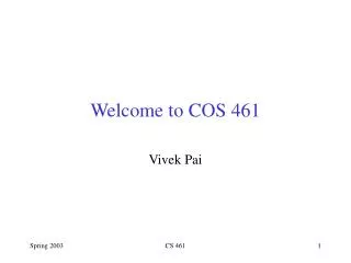
COS 461: Computer Networks Midterm Review. Spring 2011 Mike Freedman http://www.cs.princeton.edu/courses/archive/spr11/cos461/. IP. IP. IP. Ethernet interface. Internet layering: Message, Segment, Packet, and Frame. host. host. HTTP message. HTTP. HTTP. TCP segment. TCP. TCP.

E N D
COS 461: Computer NetworksMidterm Review Spring 2011 Mike Freedman http://www.cs.princeton.edu/courses/archive/spr11/cos461/
IP IP IP Ethernet interface Internet layering:Message, Segment, Packet, and Frame host host HTTPmessage HTTP HTTP TCP segment TCP TCP router router IP packet IP packet IPpacket IP Ethernet interface SONET interface Ethernet interface Ethernet interface SONET interface Ethernetframe SONET frame 2 Ethernet frame
Topics • Link layer (Sl.4) • Sharing a link: TDMA, FDMA • Ethernet and CSMA/CD • Wireless and CSMA/CA • Spanning tree and switching • Translating addrs: DHCP / ARP • Network layer (Sl.25) • IPv4 and addressing • IP forwarding • Middleboxes: NATs, firewalls, tunneling • Transport layer (Sl.38) • Socket interface • UDP • TCP • Reliability • Congestion Control • Interactions w/ Active Queue Management • Application layer (Sl.68) • Translating names: DNS • HTTP and CDNs • Overlay networks
Link-Layer Services • Encoding • Representing the 0s and 1s • Framing • Encapsulating packet into frame, adding header and trailer • Using MAC addresses, rather than IP addresses • Error detection • Errors caused by signal attenuation, noise. • Receiver detecting presence of errors
Multiple Access Protocol • Single shared broadcast channel • Avoid having multiple nodes speaking at once • Otherwise, collisions lead to garbled data • Multiple access protocol • Distributed algorithm for sharing the channel • Algorithm determines which node can transmit • Classes of techniques • Channel partitioning: divide channel into pieces • Time-division multiplexing, frequency division multiplexing • Taking turns: passing a token for right to transmit • Random access: allow collisions, and then recover
Key Ideas of Random Access • Carrier Sense (CS) • Listen before speaking, and don’t interrupt • Checking if someone else is already sending data • … and waiting till the other node is done • Collision Detection (CD) • If someone else starts talking at the same time, stop • Realizing when two nodes are transmitting at once • …by detecting that the data on the wire is garbled • Randomness • Don’t start talking again right away • Waiting for a random time before trying again
Medium Access Control in 802.11 • Collision avoidance, not detection • First exchange control frames before transmitting data • Sender issues “Request to Send” (RTS), including length of data • Receiver responds with “Clear to Send” (CTS) • If sender sees CTS, transmits data (of specified length) • If other node sees CTS, will idle for specified period • If other node sees RTS but not CTS, free to send • Link-layer acknowledgment and retransmission • CRC to detect errors • Receiving station sends an acknowledgment • Sending station retransmits if no ACK is received • Giving up after a few failed transmissions
Scaling the Link Layer • Ethernet traditionally limited by fading signal strength in long wires • Introduction of hubs/repeaters to rebroadcast • Still a maximum “length” for a Ethernet segment • Otherwise, two nodes might be too far for carrier sense to detect concurrent broadcasts • Further, too many nodes in shorter Ethernet can yield low transmissions rates • Constantly conflict with one another
Bridges/Switches: Traffic Isolation • Switch breaks subnet into LAN segments • Switch filters packets • Frame only forwarded to the necessary segments • Segments can support separate transmissions switch/bridge segment hub hub hub segment segment
Self Learning: Building the Table • When a frame arrives • Inspect the source MAC address • Associate the address with the incoming interface • Store the mapping in the switch table • Use a time-to-live field to eventually forget the mapping B A C Switch learns how to reach A D 13
Solution: Spanning Trees • Ensure the topology has no loops • Avoid using some of the links when flooding • … to avoid forming a loop • Spanning tree • Sub-graph that covers all vertices but contains no cycles • Links not in the spanning tree do not forward frames 14
Evolution Toward Virtual LANs R R O R R O O O O RO R O R O R O R Red VLAN and Orange VLAN Switches forward traffic as needed Group users based on organizational structure, rather than the physical layout of the building.
B A C C C’s signal strength A’s signal strength B A space CSMA: Carrier Sense, Multiple Access • Multiple access: channel is shared medium • Station: wireless host or access point • Multiple stations may want to transmit at same time • Carrier sense: sense channel before sending • Station doesn’t send when channel is busy • To prevent collisions with ongoing transfers • But, detecting ongoing transfers isn’t always possible
CA: Collision Avoidance, Not Detection • Collision detection in wired Ethernet • Station listens while transmitting • Detects collision with other transmission • Aborts transmission and tries sending again • Problem #1: cannot detect all collisions • Hidden terminal problem • Fading
CA: Collision Avoidance, Not Detection • Collision detection in wired Ethernet • Station listens while transmitting • Detects collision with other transmission • Aborts transmission and tries sending again • Problem #1: cannot detect all collisions • Hidden terminal problem • Fading • Problem #2: listening while sending • Strength of received signal is much smaller • Expensive to build hardware that detects collisions • So, 802.11 does collision avoidance, not detection
Hidden Terminal Problem A B C A and C can’t see each other, both send to B Occurs b/c 802.11 relies on physical carrier sensing, which is susceptible to hidden terminal problem
Virtual carrier sensing • First exchange control frames before transmitting data • Sender issues “Request to Send” (RTS), incl. length of data • Receiver responds with “Clear to Send” (CTS) • If sender sees CTS, transmits data (of specified length) • If other node sees CTS, will idle for specified period • If other node sees RTS but not CTS, free to send
Hidden Terminal Problem A B C • A and C can’t see each other, both send to B • RTS/CTS can help • Both A and C would send RTS that B would see first • B only responds with one CTS (say, echo’ing A’s RTS) • C detects that CTS doesn’t match and won’t send
Exposed Terminal Problem A B C D • B sending to A, C wants to send to D • As C receives B’s packets, carrier sense would prevent it from sending to D, even though wouldn’t interfere • RTS/CTS can help • C hears RTS from B, but not CTS from A • C knows it’s transmission will not interfere with A • C is safe to transmit to D
Impact on Higher-Layer Protocols • Wireless and mobility change path properties • Wireless: higher packet loss, not from congestion • Mobility: transient disruptions, and changes in RTT • Logically, impact should be minimal … • Best-effort service model remains unchanged • TCP and UDP can (and do) run over wireless, mobile • But, performance definitely is affected • TCP treats packet loss as a sign of congestion • TCP tries to estimate the RTT to drive retransmissions • TCP does not perform well under out-of-order packets • Internet not designed with these issues in mind
IP Packet Structure 4-bit Header Length 8-bit Type of Service (TOS) 4-bit Version 16-bit Total Length (Bytes) 3-bit Flags 16-bit Identification 13-bit Fragment Offset 8-bit Time to Live (TTL) 8-bit Protocol 16-bit Header Checksum 32-bit Source IP Address 32-bit Destination IP Address Options (if any) Payload
Source Address: What if Source Lies? • Source address should be the sending host • But, who’s checking, anyway? • You could send packets with any source you want • Why would someone want to do this? • Launch a denial-of-service attack • Send excessive packets to the destination • … to overload the node, or the links leading to node • Evade detection by “spoofing” • But, the victim could identify you by the source address • So, you can put someone else’s source address in packets • Also, an attack against the spoofed host • Spoofed host is wrongly blamed • Spoofed host may receive return traffic from receiver
00001100 00100010 10011110 00000101 Hierarchical Addressing: IP Prefixes 12 34 158 5 Network (24 bits) Host (8 bits) • IP addresses can be divided into two portions • Network (left) and host (right) • 12.34.158.0/24 is a 24-bit prefix • Which covers 28 addresses (e.g., up to 255 hosts)
Classful Addressing • In the olden days, only fixed allocation sizes • Class A: 0* • Very large /8 blocks (e.g., MIT has 18.0.0.0/8) • Class B: 10* • Large /16 blocks (e.g,. Princeton has 128.112.0.0/16) • Class C: 110* • Small /24 blocks (e.g., AT&T Labs has 192.20.225.0/24) • Class D: 1110* • Multicast groups • Class E: 11110* • Reserved for future use • This is why folks use dotted-quad notation!
CIDR: Hierarchal Address Allocation • Prefixes are key to Internet scalability • Address allocated in contiguous chunks (prefixes) • Routing protocols and packet forwarding based on prefixes • Today, routing tables contain ~200,000 prefixes (vs. 4B) 12.0.0.0/16 : : : 12.1.0.0/16 12.3.0.0/24 12.2.0.0/16 12.3.1.0/24 : : 12.3.0.0/16 : : : 12.0.0.0/8 12.3.254.0/24 12.253.0.0/19 12.253.32.0/19 12.253.64.0/19 12.253.96.0/19 12.254.0.0/16 12.253.128.0/19 12.253.160.0/19
Two types of addresses Provider independent (from IANA) Provider allocated (from upstream ISP) Provider allocated addresses seem to offer more potential for aggregation (and reducing routing table size), but not always so…
Scalability: Address Aggregation Provider is given 201.10.0.0/21 Provider 201.10.0.0/22 201.10.4.0/24 201.10.5.0/24 201.10.6.0/23 Routers in rest of Internet just need to know how to reach 201.10.0.0/21. Provider can direct IP packets to appropriate customer.
But, Aggregation Not Always Possible 201.10.0.0/21 Provider 1 Provider 2 201.10.6.0/23 201.10.0.0/22 201.10.4.0/24 201.10.5.0/24 Multi-homedcustomer (201.10.6.0/23) has two providers. Other parts of the Internet need to know how to reach these destinations through both providers.
CIDR Makes Packet Forwarding Harder 201.10.0.0/21 Provider 1 Provider 2 • Forwarding table may have many matches • E.g., entries for 201.10.0.0/21 and 201.10.6.0/23 • The IP address 201.10.6.17 would match both! • Use Longest Prefix Matching • Can lead to routing table expansion • To satify LPM, need to announce /23 from both 1 and 2 201.10.6.0/23 201.10.0.0/22 201.10.4.0/24 201.10.5.0/24
Internet-wide Internet Routing 4 3 5 2 6 7 1 Web server Client • AS-level topology • Destinations are IP prefixes (e.g., 12.0.0.0/8) • Nodes are Autonomous Systems (ASes) • Edges are links and business relationships
Middleboxes • “An abomination!” • Violation of layering • Hard to reason about • Responsible for subtle bugs • “A practical necessity!” • Solve real/pressing problems • Needs not likely to go away • Middleboxes are intermediaries • Interposed in-between the communicating hosts • Often without knowledge of one or both parties • Myriad uses • Network address translators • Firewalls • Tunnel endpoints • Traffic shapers • Intrusion detection systems • Transparent Web proxy caches • Application accelerators
Port-Translating NAT • Map outgoing packets • Replace source address with NAT address • Replace source port number with a new port number • Remote hosts respond using (NAT address, new port #) • Maintain a translation table • Store map of (src addr, port #) to (NAT addr, new port #) • Map incoming packets • Consult the translation table • Map the destination address and port number • Local host receives the incoming packet
Two Basic Transport Features Server host 128.2.194.242 Service request for 128.2.194.242:80 (i.e., the Web server) Client host Web server (port 80) OS Client Echo server (port 7) IP payload Demultiplexing: port numbers Error detection: checksums detect corruption
User Datagram Protocol (UDP) SRC port DST port checksum length DATA • Datagram messaging service • Demultiplexing of messages: port numbers • Detecting corrupted messages: checksum • Lightweight communication between processes • Send messages to and receive them from a socket • Avoid overhead and delays of ordered, reliable delivery
Transmission Control Protocol (TCP) • Stream-of-bytes service • Sends and receives a stream of bytes, not messages • Reliable, in-order delivery • Checksums to detect corrupted data • Sequence numbers to detect losses and reorder data • Acknowledgments & retransmissions for reliable delivery • Connection oriented • Explicit set-up and tear-down of TCP session • Flow control • Prevent overflow of the receiver’s buffer space • Congestion control • Adapt to network congestion for the greater good
Establishing a TCP Connection B A SYN Each host tells its ISN to the other host. SYN ACK ACK Data Data • Three-way handshake to establish connection • Host A sends a SYNchronize(open) to the host B • Host B returns a SYN ACKnowledgment (SYN ACK) • Host A sends anACK to acknowledge the SYN ACK
TCP “Stream of Bytes” Service Host A Byte 0 Byte 1 Byte 2 Byte 3 Byte 80 Host B Byte 0 Byte 1 Byte 2 Byte 3 Byte 80
…Emulated Using TCP “Segments” Host A Byte 0 Byte 1 Byte 2 Byte 3 Byte 80 • Segment sent when: • Segment full (Max Segment Size), • Not full, but times out, or • “Pushed” by application. TCP Data TCP Data Host B Byte 0 Byte 1 Byte 2 Byte 3 Byte 80
Reliability: TCP Acknowledgments Host A ISN (initial sequence number) Sequence number = 1st byte TCP HDR TCP Data ACK sequence number = next expected byte TCP HDR TCP Data Host B
Packet Packet Packet Packet Packet ACK ACK ACK ACK ACK Detecting losses Timeout Timeout Timeout Packet Timeout Timeout Timeout Packet lost ACK lost DUPLICATE PACKET Early timeout DUPLICATEPACKETS
Flow control: Sliding window Sending process Receiving process TCP TCP Last byte read Last byte written Last byte ACKed Next byte expected Last byte sent Last byte received • Allow a larger amount of data “in flight” • Allow sender to get ahead of the receiver • … though not too far ahead
Where Congestion Happens: Links • Simple resource allocation: FIFO queue & drop-tail • Access to the bandwidth: first-in first-out queue • Packets transmitted in the order they arrive • Access to the buffer space: drop-tail queuing • If the queue is full, drop the incoming packet
TCP Congestion Window • Each TCP sender maintains a congestion window • Maximum number of bytes to have in transit • I.e., number of bytes still awaiting acknowledgments • Adapting the congestion window • Decrease upon losing a packet: backing off • Increase upon success: optimistically exploring • Always struggling to find the right transfer rate • Both good and bad • Pro: avoids having explicit feedback from network • Con: under-shooting and over-shooting the rate
Leads to the TCP “Sawtooth” Window Loss halved t But, could take a long time to get started!