GEO Visible Calibration Strategy Using MODIS as Reference
This paper presents a comprehensive strategy for GEO visible calibration using MODIS as a reference. It covers inter-calibration methods, demonstrating new calibration results and trends under legacy systems. Key techniques include LEO-GEO and GEO-GEO pixel matching to ensure high accuracy in calibration. The new calibration server and website facilitate timely dissemination of calibration equations and enable effective monitoring of calibration datasets. The automation of processing enhances reproducibility, enabling side-by-side comparisons of monthly and trend differences across various satellite reference sources.

GEO Visible Calibration Strategy Using MODIS as Reference
E N D
Presentation Transcript
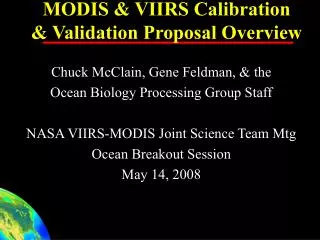
GEO Visible Calibration Strategy Using MODIS as Reference Louis Nguyen, David R. Doelling, Patrick Minnis, NASA Langley Research Center Hampton, Virginia, USA Lance A. Avey, Thad Chee, and Douglas A. Spangenberg Space Systems and Applications, Inc Hampton, Virginia, USA
Overview • Inter-Calibration Methods • VIS calibration results under legacy system • Demo New Calibration Server and Website • New VIS calibration trends from MODIS
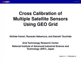
Inter-Calibration Methods • Technique 1: LEO-GEO (ex: MODIS-GOES12) • • Co-locate GEO & Polar pixels and average to 0.5° regions using 30° x 20° grid box near GEO subsatellite point • • Match solar, viewing and azimuth angles and time: • SZA < 5° VZA < 10° RAZ < 15° Time < 15min no glint • Technique 2: GEO-GEO (ex: GOES12-GOES10) • • Match pixels from 0.5 or 1° regions straddling the bisecting longitude at solar noon • • Ensures matched SZA and VZA • • Match image time within 15 minutes • Normalize all solar channels to common solar constants • Normalize each radiance to a common SZA • Perform linear regression
Slope = 1.027 SEE = 8.7 Slope = 0.6964 SEE = 7.3 GOES Calibration using VIRS Use LEO-GEO technique to directly calibrate GOES-8 & GOES-12 with VIRS GOES-8 Oct 2002 GOES-12 Feb 2004 SEE = 7.3
Time Series of GOES-8 Slope Trend GOES-8 Gain Trend Jan 1998 - Mar 2003 SEE = 0.00848 SEE/Mean = 0.891%
Nov 1998 - Mar 2003 Apr 2003 - Aug 2005 GOES-10 Calibration Using G8 & G12 Use GEO-GEO technique to transfer VIRS calibrated GOES-8 & GOES-12 to GOES-10
Time Series of GOES-10 Slope Trend SEE = 0.00716 SEE/Mean = 0.927%
GOES-12 Slope Trends SEE = 0.00375 SEE/Mean = 0.547%
Motivation for Calibration Server and Website - Dissemination of post-launch calibration equations in timely manner • For public and in-house use (GEO cloud retrieval algorithm) - Traceability • Utilize database to track and control datasets and algorithms • Version control for publishing post-launched calibration equations • Results are reproducible via cloning dataset and algorithms - Analysis of Calibration Results • Allows side-by-side comparison of monthly and trend differences in reference calibration source (TERRA-AQUA, VIRS, DDC, etc) • Results are controlled under “research” and “published” versions • Allows tweaking of algorithms under predefined parameter list - Automation: Processing and Re-processing of Calibration Data • Calibration performed under controlled Web environment • More automated and less tedious; time serie trends, monthly plots, calibration equations are updated automatically in one process • Plots are generated on demand, calibration equations published on website are pulled from database
NASA-Langley Calibration System Flowchart Data Acquisition Server (McIDAS) Orbital prediction program determines collection Store on Archive GEO Data MODISData VIRS Data AVHRR Data Deep Convective Cloud Satellite Pair Gridding Channels and region DATABASE DDC Monthly PDF Matching: spatial and temporal Web Server Interface Processing, analysis, display, dissemination Monthly Regression Constrain time, angles, glint, sigma Plots: monthly and trendline
Demo: End of Demo End of DEMO Let’s go straight to the VIS Calibration Results
MTSAT-1R Visible Gain Trend 8-bit^2 data 10-bit data