Wireless Link: Adaptation
Explore adaptive strategies in wireless networks to optimize system parameters for energy efficiency and performance. Understand the interplay of various knobs and layers, coordination of adaptation, and overall adaptation frameworks. Consider application requirements, protocol stacks, and information exchange across layers.

Wireless Link: Adaptation
E N D
Presentation Transcript
Wireless Link: Adaptation EE206A (Spring 2002): Lecture #7
Reading • Mandatory • Rex Min and Anantha Chandrakasan. A Framework for Energy-scalable Communication in High-density Wireless Networks. ACM ISLPED, 2002. • Curt Schurgers, Vijay Raghunathan, and Mani Srivastava. Power Management for Energy Aware Communication Systems. Technical Report, 2002. • Recommended • Curt Schurgers, Mani B. Srivastava. Energy Efficient Wireless Scheduling: Adaptive Loading in Time. IEEE WCNC, 2002. • Modiano, E. An adaptive algorithm for optimizing the packet size used in wireless ARQ protocols. Wireless Networks, vol.5, (no.4), Baltzer, 1999. p.279-86. • Vijay Raghunathan, Saurabh Ganeriwal, Curt Schurgers, and Mani Srivastava. E2WFQ: An Energy-Efficient Fair Scheduling Policy for Wireless Systems. • P. Lettieri, C. Schurgers, and M. B. Srivastava. Adaptive Link Layer Strategies for Energy Efficient Wireless Networking. ACM/Baltzer Wireless Networks, vol.5, (no.5), Baltzer, October 1999. p.339-55. • Note: look for the papers at http://nesl.ee.ucla.edu/pw/ee206a/.
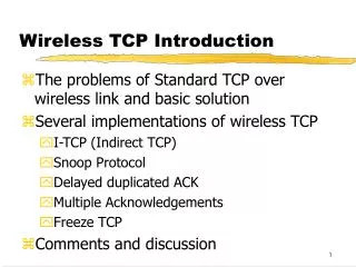
Adaptivity is Key to Wireless Systems • Time-varying environment • Fading, noise level, distance etc. • Time varying application requirements • rate, delay, error rate, # of users, energy etc. • Adapting system parameters can be used for • Wider operation range • Optimization of some cost function of the unspecified application-level variables • e.g. energy, # of users, total “utility” etc.
Some Possibilities Parameters System Functions Application Compression rate Presentation Data resolution Transport FEC type, amount Network Frame length Data Link MAC Spreading gain Physical Transmit power
Example #1: Spreading Gain Adaptation 100 PG=12 dB 80 60 DSSS Modem Chip with Adaptable Spreading Code PG=15 dB throughput x x x x x x x 40 20 PG=15 dB 0 x -15 -10 -5 0 5 Signal-to-interference ratio • Bit rate & robustness trade-off Any communication is better than none!
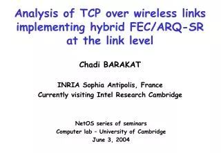
14 12 10-4 Increasing BER 10 10-3 8 Tx Energy per useful bit (J/bit) Goodput (normalized) 6 4 10-8 2 0 200 400 600 800 1000 1200 1400 Optimum for 1E-4 Packet Length (bytes) Packet Length (bytes) Example #2: Frame Length Adaptation • Adapting frame length saves link from dying in harsh channel conditions
10 9 Optimal Code Rate & Packet Length Selecting Optimal Code Rate 10-2 8 8x10⁻³ 7 6 4x10⁻³ 5 4 10-3 Energy per useful bit (J/bit) 3 10-8 2 0 200 400 600 800 1000 1200 1400 Packet Length (bytes) Example #3: Joint Code Rate & Frame Length Adaptation • Adapting code rate first, and then frame length, provides robust link & reduced battery consumption.
QoSmanager QoSmeasurement compression &playout control ReactiveApplication admissioncontrol response multilevelQoS compressionratio changes inQoS level Operating System Routingtable RoutingDaemon Network change in QoS level & mobility events admissioncontrolresponse multilevelQoS compressionratio error control,frame length, & packet scheduling AdaptiveLink channelmodel estimator Link controller mode X spread code SIR Scalable CODEC Adaptable Radio Example #4: Joint Adaptation of Radio and CODEC
Lower Layer Knobs • RF • Transmit power • Carrier frequency • Antenna direction • Baseband • Coding (symbol-level) • Modulation • Spreading gain • Equalization • Link/MAC • Frame length • Coding (packet-level)
Conceptual Framework G : I V E N - Radio characteristics (e.g. power) and capabilities (e.g. range of symbol rates) - Time-varying Channel - Quality of Service O : P T I M I Z E - Minimize energy subject to rate, delay, and BER requirement - Maximize rate subject to energy, delay, and BER requirements - etc. S L & P L P E L E C T I N K H Y S I C A L A Y E R A R A M E T E R S Adapt - Frame Length - Spreading Gain - Hybrid FEC/ARQ Error Control Scheme Link layer retransmission (ARQ) e.g. SACK Channel coder (forward error correction - FEC) block codes e.g. Reed-Solomon convolutional codes - Symbol Rate, Carrier Frequency, Power etc.
Issues • How do these knobs affect the cost function? • How to coordinate the adaptation of the various knobs? • What is the overall adaptation framework? • What is the appropriate place (or places) in the protocol stack to do the adaptation? • Some knobs are end-to-end, other are link-level • Traditionally, protocol stacks are modular, with little information exchange across layers • In wireless, performance of layers are closely coupled • How to do the needed information exchange across the layers? • e.g. how to give channel state information to, say, an application? • Interplay of RF and electronics/computing • Complex relationship between application requirements and radio parameters • e.g. application seen data rate != radio bit rate • due to bit error rate, protocol overhead, retransmissions etc. • Estimates available at receiver while the knobs are often at the transmitter • delay in the control loop • Multiple conflicting objectives (cost functions) Rather complex problem!
BER 256-QAM 16-QAM 64-QAM 4-QAM SNR (dB) 256-QAM 64-QAM SNR 16-QAM 4-QAM No transmission time Case Study #1: Exploiting the Modulation Knob • Fixed transmit power • Target performance (BER) • Adapt modulation • Varying channel SNR • Maximize throughput Throughput TraditionalAdaptiveModulation
64-QAM Required Rb 16-QAM 4-QAM time No transmission Alternative: Exploiting the Modulation Knob for Energy Ebit(J) • Slow varying SNR • Target performance (BER) • Adapt modulation • Varying load Rb • Minimize energy Ebit 4-QAM 16-QAM 64-QAM SNR = 10 dB SNR = 16 dB SNR = 22 dB SNR = 28 dB Rb(Mbit/s) Energy ModulationScaling
Ebit b = 6 b b = 4 b = 4 b = 2 b = 2 Tbit Modulation Scaling Shutdown b = 0 • The energy - delay curve is convex Slowing down is more energy efficient than shutting down • For energy efficiency, operate as slow as possible Energy Slowdown L·Ebit L·Tbit
Energy Consumption of Transmitting a Packet Ptransmit Power consumed by the power amplifier, depends on the required performance and the wireless channel (distance, fading, etc.) Pelectronics Power consumed by the electronic circuitry for filtering, upconverting, modulation, frequency synthesis, etc. Eoverhead Energy consumption that is independent of the packet size and modulation scheme (startup cost, fixed encoded header, etc.) Tbit Time to transmit one bit (depends on modulation and symbol rate Rs) L Size of packet payload H Size of packet header
Energy Consumption of Transmitting a Bit : Optimize modulation Minimize overhead Minimize header size Independent of modulation Modulation Scaling Function of the target performance, only very weakly dependent on b =1 when no variable symbol rate provision
Operate at Max Symbol Rate It is preferable to operate at the maximum symbol rate that can be implemented efficiently (i.e. without severe penalty) The energy is a function of the modulation level: there is an optimum value of b, which depends on the parameters of the system
Energy per Bit Region of modulation scaling Rs (Mbaud) b (bits/symbol)
b = 6 Ptransmit = 36 mW Ptransmit = 9 mW b = 4 Ptransmit = 2.25 mW b = 2 Energy-Delay Trade-off
Controlling the Modulation Scaling Knob • Who controls the modulation scaling knob? • One possibility: packet scheduler • Normally wireless packet schedulers decide • Which node transmits • What packet • At what time • With modulation scaling, the scheduler decides • Which node transmits • What packet • At what time • What modulation setting
packet stream 1 packet stream 2 … packet stream N Example 1: Deadline-driven Packet Scheduling with DMS • A set of real-time packet streams need to be transmitted over a common communication channel • The packets in each stream have a deadline • The streams have different periods and variable packet sizes • Goal: schedule the transmission of the individual packets such that their deadlines are not violated • Non-preemptive real-time scheduling
Non-preemptive EDF Scheduling TA TA A A A packet stream 1 TB TB B B B packet stream 2 TC C C packet stream 3 Non-preemptive EDF (earliest deadline first) scheduling TA TB TC TA TB C A A B A B C B
T1 T2 T3 fl(l) T4 L L l T5 Scheduling Set-up • Schedule a set of streams with • different periods and random offsets • uniformly random packet size
TA TB TC TA Admission step (off-line) C A A B A B C static C A B A B C C A B A C B dynamic C C Adjustment step (on-line) A A B B stretch C C A A B B Real-time Packet Scheduling with DMS [Schurgers @ Globecom-2002]
Simulation Scenario #1 E/E0 static dynamic static· dynamic static· dynamic· stretch Utilization (=1): 84%
Simulation Scenario #2 E/E0 dynamic static· dynamic static Utilization (=1): 64% static· dynamic· stretch
Ebit Tbit Summary of Deadline-driven Packet Scheduling with DMS • Modulation level provides a control-knob to introduce energy-awareness in communication systems • Dynamic Modulation Scaling (DMS) is part of the power management subsystem. Real-time energy aware packet scheduling results in energy savings by leveraging: • Variations in worst-case traffic load: static • Variations in packet size: dynamic· stretch
Example 2: Packet Fair Queuing with DMS • Recap GPS & WFQ • In GPS each infinitely divisible backlogged stream is guaranteed a rate • WFQ is a packet approximation of GPS • Compute finish times of packets under GPS • Earliest Finish Time First (EFTF) scheduling • Diff. in pkt. delays between GPS and WFQ is (Lmax / C)
Tokens i i Recap Continued • Leaky bucket mechanism • Regulate and police traffic in a network • Amount of traffic that enters the networkin (,t) is: • i average rate, i burstiness • GPS (WFQ) + Leaky-bucket • i gi for session to be stable • Worst case delay guarantee using GPS is given by:
E2WFQ : Combining DMS & WFQ[Raghunathan @ ISLPED-2002] • Intuitively, what does fairness mean? • Each connection gets no more than what it wants (subject to a max.) • The excess, if any, is equally shared • In E2WFQ, excess is not distributed Used to save energy instead • Energy saving opportunities • Average input rate of a stream is lower then guaranteed rate • Packet lengths may be variable (often shorter than worst case) • Low, time varying link utilization
E2WFQ Algorithm • Goal of algorithm • Vary the output rate to match the current workload (demand) • Bound the performance impact due to output rate variation • Basic steps of the algorithm • Monitor the instantaneous workload • Calculate the output rate to match the instantaneous workload • Set the output link speed
E2WFQ Algorithm (contd.) • Monitoring the input rate • Queue size is a good indicator of instantaneous arrival rate • Input rate suddenly increases ==> queue size increases • Parameter is defined to be the desired time from a packet’s arrival at the end of queue to its departure from head of queue. • Compute the required output rate • For flow i, required rate for k’th pkt. to have a total delay of is: • Required rate for a flow is simply the maximum over all flows • Output link rate can be calculated as
E2WFQ Algorithm (contd.) • Change the output link speed • The new modulation level can be calculated as: • If R < C, transmissions can be slowed, resulting in energy savings • Accounting for variable packet sizes • Variation in packet sizes can be exploited to further scale down the modulation level • The new required rate for a packet is given by:
Rnew Low High Rold What is ? • determines the system’s response to workload variations • is the time constant of the first order input response to the system • is related to the bandwidth of the low pass filter through which the input rate is filtered • determines the maximum impact on packet delays • The maximum delay of a packet of stream i, under E2WFQ is:
Choice of • Best choice of depends on: • Allowable latency hit • Input rate variability • High value of system responds sluggishly to input variations, filtering out steep workload transients • Because of Jensen’s inequality and the convexity of energy-speed curve, this yields higher energy savings. • However, high value of increases the packet delays
Simulation Results • Significant energy savings • Energy savings increase as link utilization decreases • For a given utilization energy savings increase burstiness decreases
Simulation Results (contd.) • Output rate follows input rate • Increases in steps of (Li / )
Simulation Results (contd.) • Distribution of packet delays • Most packets have a delay of • No delay bound violations (D=200 ms, =50 ms, (Lmax/Cmin)=2 ms)
T L bits at bav time Example 3: Scheduling with DMS in Time Varying Channels • Select the transmit power and constellation size as a function of: • Time varying wireless channel • Target average throughput • Goal: • Minimize the total energy consumption • Constant BER • Observations • As the SNR drops, we need more energy for the same throughput • For the same SNR, transmitting slower can save energy
The Scheduling Problem • More energy efficient to send information when the channel is good • Whether or not it is more efficient to more bits now or later depends on the future channel behavior Scheduling issue ? Channel gain time
BER 256-QAM 16-QAM 64-QAM 4-QAM SNR (dB) Difference from Adaptive Modulation • Fixed transmit power • Target performance (BER) • Adapt modulation • Varying channel SNR • Maximize throughput • The best modulation level is chosen based on the current channel condition alone • No scheduling issue
Channel gain time Channel gain frequency Analogy with OFDM Bit Loading • Multicarrier system (wired and wireless) • Frequency band is split up in a large set of parallel subcarriers • Each subband carries is low-rate data stream • Adaptive loading to improve performance • Given a data rate constraint • Assign power and bits to each subcarrier to minimize total power • Adaptive loading in time • We need to know the channel condition for the entire time epoch • Number points is large
Adaptive Loading b = 2 b = 4 b = 6 • Assign bi and Pi such that • Target throughputbav • Minimize powerPav Constellation size bi (bits/symbol) N = 256 bav = 4 Normalized channel response (dB) Subcarrier
Channel gain (~SNR) d4 b = 8 b = 6 b = 4 b = 2 b = 0 d3 d2 d1 Time (s) Loading in Time • Abstract correlation: equivalent number N of independent points • N is large in the case of loading in time • One can show that when N , adaptive loading reduces to thresholding
bav (bits/symbol) d2 d3 d1 d4 approximation thresholds Threshold Values Thresholds are related as: • The only independent parameter d1 is a function of the statistics of the channel gains and the target average throughput • For Rayleigh fading, it is given by: Bit assignment is only dependent on the current channel state and given by:
Validating Loading in Time • The achieved average throughput as a function of time • Mean value is equal to the target throughput • The variance decreases with N bav = 8 bav = 6 bav = 4 fb(b) bav = 2 N b(bits/symbol)
bav - 4 · bav + 4 · fb(b) b(bits/symbol) Soft Deadline • 99.99% of the throughput is in the range of [bav-4· , bav+4·] • Goal is to send L bits in T seconds b b T slack L bits at bav time
Channel gain Time (s) Alternative Schemes • Loading in time • Transmit at bav = b + b • Constant b • Transmit at b • Do not consider channel condition • Maximum throughput • Adaptive modulation with fixed transmit power • No scheduling issue • Non-time varying channel • Transmit at b, but channel is AWGN
Ebit (J) Max. throughput Constant b Loading in time Non time-varying channel bav Simulation of Loading in Time Only transmit when channel is very good shutdown 0 dB Channel gain time