Download
1 / 46
1.16k likes | 2.24k Vues
Chapter 5 Transistor Bias Circuits. Objectives. Discuss the concept of dc biasing of a transistor for linear operation. Analyze voltage-divider bias, base bias, and collector-feedback bias circuits. Basic troubleshooting for transistor bias circuits. Objectives Introduction

E N D
Objectives • Discuss the concept of dc biasing of a transistor for linear operation • Analyze voltage-divider bias, base bias, and collector-feedback bias circuits. • Basic troubleshooting for transistor bias circuits
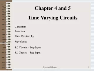
Objectives Introduction DC operating point Voltage-divider bias Other bias methods Base bias Emitter bias Collector-feedback bias Troubleshooting Summary Lecture’s outline
Introduction • The term biasing is used for application of dc voltages to establish a fixed level of current and voltage. • Transistor must be properly biased with dc voltage to operate as a linear amplifier. • If amplifier is not biased with correct dc voltages on input and output, it can go into saturation or cutoff when the input signal applied. • There are several methods to establish DC operating point. • We will discuss some of the methods used for biasing transistors.
The DC Operating Point • The goal of amplification in most cases is to increase the amplitude of an ac signal without altering it. • Improper biasing can cause distortion in the output signal.
The DC Operating Point The purpose of biasing a circuit is to establish a proper stable dc operating point (Q-point). The dc operating point between saturation and cutoff is called the Q-point. The goal is to set the Q-point such that that it does not go into saturation or cutoff when an ac signal is applied.
Q-point of a circuit: dc operating point of amplifier specified by voltage and current values (VCE and IC). These values are called the coordinates of Q-point. Refer to figure a, given IB = 200μA and βDC=100. IC=βDCIB so IC=20mA and Figure b, VBB is increased to produce IB of 300μA and IC of 30mA. Figure c, VBB is increased to produce IB of 400μA and IC=40mA. So, VCE is:
DC Operating Point-DC load line • Recall that the collector characteristic curves graphically show the relationship of collector current and VCE for different base currents. • When IB increases, IC increases and VCE decreases or vice-versa. Each separate Q-point is connected through dc load line. At any point along line, values of IB, IC and VCE can be picked off the graph. • Dc load line intersect VCE axis at 10V, where VCE=VCC. This is cutoff point because IB and IC zero. Dc load line also intersect IC axis at 45.5mA ideally. This is saturation point because IC is max and VCE=0.
DC Operating Point-Linear operation • Region between saturation and cutoff is linear region of transistor’s operation. The output voltage is ideally linear reproduction of input if transistor is operated in linear region. • Let’s look at the effect a superimposed ac voltage has on the circuit. IB vary sinusoidally 100μA above and below Q-point of 300μA. IC vary up and down 10mA of its Q-point(30mA). VCE varies 2.2V above and below its Q-point of 3.4V. • However, as you might already know, applying too much ac voltage to the base would result in driving the collector current into saturation or cutoff resulting in a distorted or clipped waveform. • When +ve peak is limited, transistor is in cutoff. When –ve peak is limited, transistor is in saturation.
Graphical load line illustration of transistor being driven into saturation or cutoff
Determine Q-point in figure below and find the maximum peak value of base current for linear operation. Assume βDC=200. Example 1
Q-point is defined by values of IC and VCE. Q-point is at IC=39.6mA and VCE=6.93V. Since IC(cutoff)=0, we need to know IC(sat) to determine variation in IC can occur and still in linear operation. Before saturation is reached, IC can increase an amount equal to: IC(sat) – ICQ = 60.6mA – 39.6mA = 21mA. Solution
However, IC can decrease by 39.6mA before cutoff (IC=0) is reached. Since the gap of Q-point with saturation point is less than gap between Q-point and cutoff, so 21mA is the max peak variation of IC. The max peak variation of IB is: Solution cont..
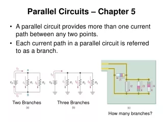
Voltage-Divider Bias • Voltage-divider bias is the most widely used type of bias circuit. Only one power supply is needed and voltage-divider bias is more stable( independent) than other bias types. For this reason it will be the primary focus for study. • dc bias voltage at base of transistor is developed by a resistive voltage-divider consists of R1 and R2. • Vcc is dc collector supply voltage. 2 current path between point A and ground: one through R2 and the other through BE junction and RE.
Voltage divider bias • If IB is much smaller than I2, bias • circuit is viewed as voltage divider • of R1 and R2 as shown in Figure a. • If IB is not small enough to be • neglected, dc input resistance • RIN(base) must be considered. • RIN(base) is in parallel with R2 as • shown in figure b.
Input resistance at transistor base • VIN is between base and ground and IIN is the current into base. • By Ohm’s Law, • RIN(base) = VIN / IIN • Apply KVL, VIN=VBE+IERE • Assume VBE<<IERE, so VIN≈IERE • Since IE≈IC=βDCIB, • VIN≈ βDCIBRE • IN=IB, so • RIN(base)= βDCIBRE / IB • RIN(base) = DCRE
Total resistance from base to ground is: A voltage divider is formed by R1 and resistance from base to ground in parallel with R2. If DCRE>>R2, (at least ten times greater), then the formula simplifies to Analysis of voltage divider bias circuit
Now, determine emitter voltage VE. VE=VB – VBE Using Ohm’s Law, find emitter current IE. IE = VE / RE All the other circuit values IC≈ IE VC = VCC – ICRC To find VCE, apply KVL: VCC – ICRC – IERE – VCE =0 Since IC≈ IE, VCE≈ VCC – IC (RC + RE) Analysis of Voltage-Divider Bias Circuit
Determine VCE and IC in voltage-divider biased transistor circuit below if βDC=100. Example 2
Determine dc input resistance at base to see if it can be neglected. RIN(base)=10R2, so neglect RIN(base). Then, find base voltage So, emitter voltage And emitter current Thus, And VCE is Solution
Voltage-Divider Bias for PNP Transistor Pnp transistor has opposite polarities from npn. To obtain pnp, required negative collector supply voltage or with a positive emitter supply voltage. The analysis of pnp is basically the same as npn.
Base voltage Emitter voltage By Ohm’s Law, And, Analysis of voltage bias for pnp transistor
BASE BIAS EMITTER BIAS COLLECTOR-FEEDBACK BIAS OTHER BIAS METHODS
KVL apply on base circuit. VCC – VRB – VBE = 0 or VCC – IBRB – VBE =0 Solving for IB, Then, apply KVL around collector circuit. VCC – ICRC – VCE = 0 We know that IC = βDCIB, Other bias methods - Base Bias
From the equation of IC, note that IC is dependent on DC. When DC vary, VCE also vary, thus changing Q-point of transistor. This type of circuit is beta-dependent and very unstable. Recall that DCchanges with temperature and collector current. Base biasing circuits are mainly limited to switching applications. Base bias
Emitter Bias Npn transistor with emitter bias
This type of circuit is independent of DCmaking it asstable as the voltage-divider type. The drawback is that it requires two power supplies. Apply KVL and Ohm’s Law, IBRB + IERE + VBE = -VEE Since IC≈IE and IC= DC IB, Solve for IE or IC, Voltage equations for emitter base circuit. VE = VEE + IERE VB = VE + VBE VC = VCC – ICRC Emitter base
Collector-Feedback Bias Collector-feedback bias is kept stable with negative feedback, although it is not as stable as voltage-divider or emitter.With increases of IC, VC decrease and causing decrease in voltage across RB, thus IB also decrease. With less IB ,IC go down as well.
By Ohm’s Law, Collector voltage with assumption IC>>IB. VC = VCC – ICRC And IB = IC / DC So, collector current equation Since emitter is ground, VCE = VC. VCE = VCC - ICRC Analysis of collector-feedback circuit
Troubleshooting Figure below show a typical voltage divider circuit with correct voltage readings. Knowing these voltages is a requirement before logical troubleshooting can be applied. We will discuss some of the faults and symptoms.
Troubleshooting Fault 2: Resistor RE Open Transistor is in cutoff. Base reading voltage will stay approximately the same. Since IC=0, collector voltage goes up to 10 V(VCC). Emitter voltage will be approximately the base voltage - 0.7 V. Fault 1: R1 Open With no bias the transistor is in cutoff. Base voltage goes down to 0 V. Collector voltage goes up to10 V(VCC). Emitter voltage goes down to 0 V.
Troubleshooting Fault 3: Base lead internally open Transistor is nonconducting (cutoff), IC=0A . Base voltage stays approximately the same, 3.2V. Collector voltage goes up to 10 V(VCC). Emitter voltage goes down to 0 V because no emitter current through RE. Fault 4: BE junction open Transistor is in cutoff. Base voltage stays approximately the same,3.2V. Collector voltage goes up to 10 V(VCC) Emitter voltage goes down to 0 V since no emitter current through RE.
Troubleshooting Fault 5: BC junction open Base voltage goes down to 1.11 V because of more base current flow through emitter. Collector voltage goes up to 10 V(VCC). Emitter voltage will drop to 0.41 V because of small current flow from forward-biased base-emitter junction.
Troubleshooting Fault 6: RC open Base voltage goes down to 1.11 V because of more current flow through the emitter. Collector voltage will drop to 0.41 V because of current flow from forward-biased collector-base junction. Emitter voltage will drop to 0.41 V because of small current flow from forward-biased base-emitter junction.
Troubleshooting Fault 7: R2 open Transistor pushed close to or into saturation. Base voltage goes up slightly to 3.83V because of increased bias. Emitter voltage goes up to 3.13V because of increased current. Collector voltage goes down because of increased conduction of transistor.
Summary • The purpose of biasing is to establish a stable operating point (Q-point). • The Q-point is the best point for operation of a transistor for a given collector current. • The dc load line helps to establish the Q-point for a given collector current. • The linear region of a transistor is the region of operation within saturation and cutoff.
Summary • Voltage-divider bias is most widely used because it is stable and uses only one voltage supply. • Base bias is very unstable because it is dependent. • Emitter bias is stable but require two voltage supplies. • Collector-back is relatively stable when compared to base bias, but not as stable as voltage-divider bias.