Download

1 / 38
380 likes | 577 Vues
Intrinsic Rotation in JET. M. F. F. Nave 22 nd March 2010. This talk. Diagnostics tools Intrinsic rotation measurements standard ripple: Ohmic heating, ICRF heating, LHCD Ripple effects on JET intrinsic rotation studied in Ohmic and ICRF

E N D
Intrinsic Rotation in JET M. F. F. Nave 22nd March 2010
This talk • Diagnostics tools • Intrinsic rotation measurements standard ripple: • Ohmic heating, ICRF heating, LHCD • Ripple effects on JET intrinsic rotation studied in Ohmic and ICRF • JET intrinsic rotation scaling (comparison with Rice’s scaling) • Observations’ conclusions • Modelling in progress Thanks to T. Johnson, A. Salmi, L. Eriksson, C. Giroud, K.-D. Zastrow, R. Sartori, P. de Vries, V. Parail, J. Mailloux and TFH (M. Mayoral, J. Ongena) ,TF T(T. Tala)
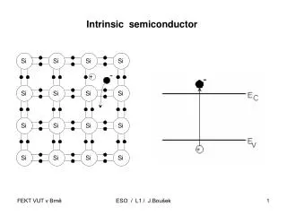
What we mean by intrinsic rotation Know sources of momentum input : NBI: this is the largest source of momentum input in present tokamaks JET: NBI drives co-current rotation in the usual Ip and Bt configuration ICRH: we can choose wave phasing to produce a small toroidal momentum in either co or counter-current direction. These will not be discuss these. Intrinsic rotation : Rotation measured in plasmas with no momentum input: such as in Ohmic ICRH: with dipole wave phasing/ minority heating LHCD
Motivation to study intrinsic rotation • In ITER and in fusion reactors: momentum input is expected to be small even with NBI • Other sources of rotation need to be found and understood. • Rice’s scaling (Rice NF 2007): inter-machine intrinsic rotation scaling predicts a significant rotation for ITER (~300km/s at edge). • WE NEED TO VERIFY IF JET ALSO FOLLOWS RICE’ SCALING LAW • As an experimental tool: We need to understand how to control the direction of rotation • Rotation is a useful experimental tool as it plays many critical roles in plasma performance: • Turbulence suppression (ExB shear) • Mode stabilisation (RWM, NTM, sawteeth etc.) • Tolerance to magnetic field errors • Onset of H-mode and ITB • Co-rotation: (e.g. better ELMy H-modes) • Counter-rotation (QH Modes, small sawteeth regimes, etc)
Rotation measurement toolsIntrinsic rotation is quite difficult to measure • (i) Charge exchange (CX) • Toroidal angular frequency profiles are obtained from charge exchange recombination spectroscopy of C+6 during NBI blips (PNBI~1MW). NBI provides a toroidal momentum source. In the normal JET configuration (BT//Ip) NBI plasmas are co-rotating. For diagnostic purposes only measurements taken within the first 30 ms can be used. • From 2007:Improved measurements () • NON- PERTURBATIVE METHODS: • (ii) X-ray crystal spectrometry (XCS) • The toroidal angular frequency in the plasma core is measured with a high resolution X-ray crystal spectrometer that observes the spectrum near the resonance line of the helium-like nickel (Ni+26) of the plasma. • Information on Ti, Te and direction and magnitude of rotation in the plasma core (T~3-8 Kev). From 2006: broken detector () • (iii) MHD mode analysis • The observed frequency of MHD modes can provide information on plasma rotation at different radial positions.
Rotation measurement toolsGood agreement from different diagnostics. • Good agreement from different diagnostics. • In this example with ICRF: XCS, CX and MHD data (sawtooth pre-cursors) indicate co-rotation Krad/s RF Ohmic
Rotation measurement tools (CX profiles at beginning of NBI blip are a good measurement of intrinsic rotation) Example: CX profile from Ohmic Plasma. A- comparison between first CX time output and "linear fit + going back in time t=t0, show very small difference from t=t1(=10 ms) B-Modelling with ASCOT (calculation of torque(t) from NBI PINI8/6) and JETTO (calculation of wf(t,r) using different models for momemtum transport) showwf10ms after onset of NBI is 10 x smaller than measured values centre
Observations with JET standard ripple (0.08%)
JET Intrinsic rotation: typical angular frequencies < 10 krad/s Vf < 30 km/s One order of magnitude smaller than in NBI plasmas that have a large momentum input I Usual Bt and Ip configuration 12MW NBI 4 MW ICRH Ohmic
Typical observed intrinsic rotation- L-mode C For the standard JET low ripple d=0.08%: Edge: co-rotating independent of scenario. CoreICRF: either co- or counter-rotating High Ip : peaked, co-rotating Low Ip: sometimes hollow, counter-rotating CoreOhmic: hollow counter-rotating CoreLHCD: either co- or counter-rotating JET database: mostly L-modes L-mode ICRF: L-G Eriksson, T Hellsten, M F F Nave et al., Plasma Phys. Control. Fusion 51 No 4 (April 2009) 044008. PICRF=4MW (NB. In all three cases Te and Ti are peaked.)
Typical observed intrinsic rotation – H-mode • Pulse from S1-2.4.6 NBI vs high ICRH fraction H-modes (SC R. Sartori) • (PRF~10MW, Ip=2.5MA, BT=2.6T , bN~1.3) Very few measurements during H-modes are available For bN up to 1.3%, H-modes more co-rotating than L-modes, however range of wf values similar to those observed in L-modes wfdoesn’t depend on PRF, Doesn’t depend on bN (Experiment T.3.1.14 to measure rotation with high PRFand/or high bN wasn’t done). Blips 2 and 3 show very small rotation <2krad/s at core and ~ 2krad.s at edge Ignore 1st blip Too close to NBI pre-heating
Typical observed intrinsic rotation – H-mode • Pulse from S1-2.4.6 NBI vs high ICRH fraction H-modes (SC R. Sartori) • (PRF~10MW, Ip=2.5MA, BT=2.6T , bN~1.3) Very few measurements during H-modes are available For bN up to 1.3%, H-modes more co-rotating than L-modes, however range of wf values similar to those observed in L-modes wfdoesn’t depend on PRF, Doesn’t depend on bN (Experiment T.3.1.14 to measure rotation with high PRFand/or high bN wasn’t done). Blips 2 and 3 show very small rotation <2krad/s at core and ~ 2krad.s at edge Ignore 1st blip Too close to NBI pre-heating
Effect of toroidal field ripple on intrinsic rotation • Following B: |B|~B0[1+ecos(q)+dsin(Nf)] oscillate due to toroidicity and ripple. • The ripple is largest in the outboard of the plasma where the plasma is close to the toroidal magnetic field coils. The ripple amplitude differs by several orders of magnitude between the plasma core and edge. • the distance between TF coils is larger on the outboard, than the inboard side. The ripple max amplitude found at the separatrix near the outboard equatorial plane. • TF ripple can impart toroidal momentum by magnetic mirror forces • trapping in the mirror between field coils
Effect of TF ripple on intrinsic rotation • JET has 32 coils – very low levels of ripple (<0.08%). • JET can increase ripple by reducing current in every second TF coil ripple was increased from 0.08% to 1.5% (ITER ripple values 0.5-1.2%) • AIMS of Intrinsic Rotation Experiments: • NBI experiments in previous JET ripple campaigns showed that ripple produced counter-rotation in plasmas with co-injected momentum. • The object of the new experiment was to find out if ripple would also affect rotation. in plasmas with no momentum input and, in the case of Ohmic plasmas without fast ions. • Separate ripple induced fast ion effects from thermal ion effects • Ripple induced fast ion losses cannot totally explain edge counter-rotation observed with NBI (P. de Vries 2007, A. Salmi 2007) • Test existing theories on the role of ripple on plasma rotation • Experimental set up: • Two plasma currents: 1.5 MA and 2.1MA (with BT-2.2T) • Ohmic and ICRF plasmas with PRF=1-4 MW, dipole Rotation Experiments with TF ripple – OHMIC ROTATION
OHMIC ROTATION with ripple • Ohmic plasmas: • Counter toroidal (and, • counter poloidal rotation) • increases with ripple
OHMIC ROTATION with ripple Counter rotation increases with ripple Similar effect on edge and core Ohmic Pulses with <BT>=2.1T, Ip=2.1MA
ICRF ROTATION with ripple Ripple produces counter rotation. The effect is larger in the plasma core, indicating that fast ions as well as thermal ion effects may be involved. L-mode/type III ELM phases more counter rotating than in type I ELM phases. . <BT>=2.1T, Ip=1.5MA, Picrf=3MW
ICRF Rotation with TF rippleFast ion losses Core counter rotation increases before a monster sawtooth crash, when core-tae modes are present and fast-ion losses observed. 104 rad/s
ICRF Rotation with TF rippleICRF resonance position Record counter rotation (~-20 krad/s) with ICRF on rhs. Pulses with 1.5% ripple ICRF off-axis ICRF on-axis
Inter-machine Scaling (J. Rice et al, NF 2007) Predicted edge toroidal rotation for ITER: wf~ 300 Km/s Large intrinsic rotation predicted for ITER, now used as argument for not needing NBI system. JET data (Mark 0 divertor, 1993) ICRF, r/a=0.3 (measured with crystal spectrometer) The high values of co-rotation ~20krads/s are no longer observed N.B. Mixes different heating schemes, ripple values, measurements at different raddii, different machine sizes. wf W/Ip
Inter-machine Scaling (J.Rice et al, NF 2007) +new JET data JET ICRF H-mode data doesn’t follow Rice’s scaling law. For 0.08% ripple Mach-Alfven ~ 10 times smaller for same bN For 0.5% ripple JET rotation ~ zero, For 1-1.5% ripple JET is counter rotating Type III Type I
Summary- Observations Toroidal intrinsic rotation has been measured in JET plasmas • Without Ripple: • Ohmic Plasmas: core counter rotating • RF Plasmas: core either counter or co- rotating depending on Ip • LHCD Plasmas: core either counter or co-rotating • Edge co-rotating independent of regime • With Ripple • Ripple has a significant effect on the rotation of both Ohmic and ICRH plasmas • Ripple drives counter rotation • Ripple effect seen both in the edge and core Ripple has to be taken into consideration when extrapolating to ITER • Rice’s Scaling and JET data • Intrinsic Rotation in JET has no clear dependency on bN • JET ICRF rotation is very low, below Rice’ scaling law. • For 0.5% ripple, JET plasmas are hardly rotating. • For 1% ripple, JET ICRF plasmas are counter rotating
Modelling in Progress:Ripple effects • Observation of increased counter-rotation in Ohmic plasmas indicates a strong torque due to non-ambipolar transport of thermal ions. • In ICRH plasmas the rotation change in the plasma core is larger indicating that the torque source in this case would be less edge localised and that fast-ion as well as thermal ion effects may be involved. • To test these hypothesis numerical modeling is being performed with the Monte Carlo codes ASCOT (A. Salmi) and SELFO (T. Johnson). • Conclusion for Ohmic Plasmas: the toroidal torque driven by non-ambipolar transport of thermal ions is found to be significant (equivalent to torque from PNBI=1.5 MW ). (A. Salmi)
Preliminary modelling results (Ohmic Plasmas) Observation of increased counter-rotation in Ohmic plasmas indicates a strong torque due to non-ambipolar transport of thermal ions. ASCOT calculation: the toroidal torque driven by non-ambipolar transport of thermal ions is found to be significant (equivalent to torque from PNBI=1.5 MW ). (A. Salmi) Observed counter rotation freq. smaller than NC residual value for r~0.9 w*NC 1/n = 3.5/(ZieBq)∂rTi~ -4.7±2.7 krad/s. w*NC1/n from K. Shaing, PoP 2003
Modelling in Progress Role of Turbulence: Explore sources of momentum in a turbulent system, leading to an understanding of observations of intrinsic rotation in Ohmic Plasmas (no ripple). (collaboration with Oxford Theoretical Physics: F. Parra, Alexander Schekochihin) How can to explain change of rotation direction in the middle of the plasma? Modelling of LH plasmas – To be started (Y. Baranov)
Ohmic Rotation with TF ripple • Ohmic plasmas: • Counter toroidal and, • counter poloidal rotation • increases with ripple 5krad/s 3.8m Toroidal rotation 3.1m 3km/s 3.6m Poloidal rotation 3.2m
Ripple pulses with PRF~3MW, Ip=1.5MA,BT=2.1T H-modes observed with Ip=1.5 MA Blip2: Type I bN~1.0 Blip3: Type III/Lmode bN~0.5-0.7 Blip1: Ohmic
Summary of previous results (no ripple) Scaling (L-mode data) Core wfa Ip Edge wfa Wdia/nel L.-G. Erickson et al. to appear in PPCF 2009
Core Toroidal rotation is sensitive to the plasma current High Ip: Peaked rotation profiles Core Co-current rotation. . Low Ip: Hollow profiles. Core counter-rotation with angular frequencies < 10 krad/s (with or without sawtooth) ICRF Heating - L-mode study (no ripple) Core (R=3.1 m)
JETTO/ ASCOT modeling for Ohmic plasmas with Ripple • Input for ASCOT calculation of toroidal torque driven by non-ambipolar transport of thermal ions: • T and n profiles (don’t not change with ripple) • Erad calculated using JETTO/NCLASS • CX toroidal velocity 2 Te keV 1 Ti Te (HRTS) and Ti (CX) for 3 ripple levels (0%-1%)
JETTO/ ASCOT modelling for Ohmic plasmas Poloidal velocity Toroidal velocity CX data Core CX data Edge r>0.8 extrapolated 1 0 -1 -2 NC 0% 2 0 -2 -4 -6 104m/s 1.5% 103m/s
JETTO/ ASCOT modeling for Ohmic plasmas Torque from thermal ions effects in Ohmic plasmas similar to torque from fast ion effects from 1-1.5 MW NBI
Observations with LHCD • (i) First measurements of rotation with LH (2 pulses) in 2007 were reported in the paper by L-G Eriksson et al., Plasma Phys. Control. Fusion 51 No 4 (April 2009) 044008. • (ii) Further measurements of rotation with LH were done parasitically during the 2008-2009 HLC of the LH . However, these experiments were not optimized for LH power penetration. • While the 2008-2009 experiments showed counter-current rotation, the earlier L-G Eriksson's pulse showed co-current rotation. • Preliminary data analysis appears to indicate that core co-current rotation might only be observed in pulses with good core LH penetration (as it was the case in L-G Eriksson' pulse). Another unknown is the effect of magnetic shear (unlike the recent pulses, the L-G Eriksson's pulse was obtained with q(0)>1). • However experiment T-3.1.15 to check the effect of LH wave penetration on rotation was never done.
New LHCD data: shows core counter-current rotationedge is always co-rotating Co-current Counter-current NB. Larger counter-rotation for n//=2.3
Previous results with LHCD: Lars-Erikson’s experiment 2007 Indicating co-rotation when LH deposition is central (?) LH LH+ICRF L.-G. Ericksson et al. PPCF 2009