Boolean Algebra
Boolean Algebra. Introduction. 1854: Logical algebra was published by George Boole known today as “Boolean Algebra” It’s a convenient way and systematic way of expressing and analyzing the operation of logic circuits.


Boolean Algebra
E N D
Presentation Transcript
Introduction • 1854: Logical algebra was published by George Boole known today as “Boolean Algebra” • It’s a convenient way and systematic way of expressing and analyzing the operation of logic circuits. • 1938: Claude Shannon was the first to apply Boole’s work to the analysis and design of logic circuits.
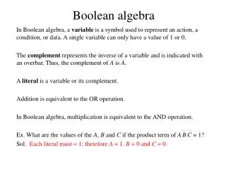
Boolean Operations & Expressions • Variable – a symbol used to represent a logical quantity. • Complement – the inverse of a variable and is indicated by a bar over the variable. • Literal – a variable or the complement of a variable.
Boolean Addition • Boolean addition is equivalent to the OR operation • A sum term is produced by an OR operation with no AND ops involved. • i.e. • A sum term is equal to 1 when one or more of the literals in the term are 1. • A sum term is equal to 0 only if each of the literals is 0. 0+1 = 1 1+0 = 1 1+1 = 1 0+0 = 0
Boolean Multiplication • Boolean multiplication is equivalent to the AND operation • A product term is produced by an AND operation with no OR ops involved. • i.e. • A product term is equal to 1 only if each of the literals in the term is 1. • A product term is equal to 0 when one or more of the literals are 0. 0·1 = 0 1·0 = 0 1·1 = 1 0·0 = 0
Laws & Rules of Boolean Algebra • The basic laws of Boolean algebra: • The commutative laws (กฏการสลับที่) • The associative laws (กฏการจัดกลุ่ม) • The distributive laws (กฏการกระจาย)
Commutative Laws • The commutative law of addition for two variables is written as: A+B = B+A • The commutative law of multiplication for two variables is written as: AB = BA A B A+B B+A B A A B AB B+A B A
Associative Laws • The associative law of addition for 3 variables is written as: A+(B+C) = (A+B)+C • The associative law of multiplication for 3 variables is written as: A(BC) = (AB)C A+B A A A+(B+C) B B (A+B)+C C C B+C AB A A A(BC) B B (AB)C C C BC
Distributive Laws • The distributive law is written for 3 variables as follows: A(B+C) = AB + AC A AB B B+C B C X X A A AC C X=AB+AC X=A(B+C)
Rules of Boolean Algebra ___________________________________________________________ A, B, and C can represent a single variable or a combination of variables.
DeMorgan’s Theorems • DeMorgan’s theorems provide mathematical verification of: • the equivalency of the NAND and negative-OR gates • the equivalency of the NOR and negative-AND gates.
DeMorgan’s Theorems • The complement of two or more ANDed variables is equivalent to the OR of the complements of the individual variables. • The complement of two or more ORed variables is equivalent to the AND of the complements of the individual variables. NAND Negative-OR NOR Negative-AND
DeMorgan’s Theorems (Exercises) • Apply DeMorgan’s theorems to the expressions:
DeMorgan’s Theorems (Exercises) • Apply DeMorgan’s theorems to the expressions:
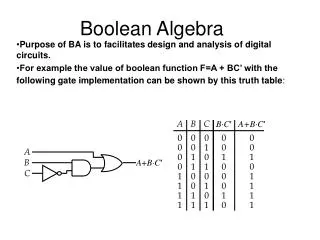
Boolean Analysis of Logic Circuits • Boolean algebra provides a concise way to express the operation of a logic circuit formed by a combination of logic gates • so that the output can be determined for various combinations of input values.
Boolean Expression for a Logic Circuit • To derive the Boolean expression for a given logic circuit, begin at the left-most inputs and work toward the final output, writing the expression for each gate. CD C D B+CD B A(B+CD) A
Constructing a Truth Table for a Logic Circuit • Once the Boolean expression for a given logic circuit has been determined, a truth table that shows the output for all possible values of the input variables can be developed. • Let’s take the previous circuit as the example: A(B+CD) • There are four variables, hence 16 (24) combinations of values are possible.
Constructing a Truth Table for a Logic Circuit • Evaluating the expression • To evaluate the expression A(B+CD), first find the values of the variables that make the expression equal to 1 (using the rules for Boolean add & mult). • In this case, the expression equals 1 only if A=1 and B+CD=1 because A(B+CD) = 1·1 = 1
Constructing a Truth Table for a Logic Circuit • Evaluating the expression (cont’) • Now, determine when B+CD term equals 1. • The term B+CD=1 if either B=1 or CD=1 or if both B and CD equal 1 because B+CD = 1+0 = 1 B+CD = 0+1 = 1 B+CD = 1+1 = 1 • The term CD=1 only if C=1 and D=1
Constructing a Truth Table for a Logic Circuit • Evaluating the expression (cont’) • Summary: • A(B+CD)=1 • When A=1 and B=1 regardless of the values of C and D • When A=1 and C=1 and D=1 regardless of the value of B • The expression A(B+CD)=0 for all other value combinations of the variables.
Constructing a Truth Table for a Logic Circuit • Putting the results in truth table format A(B+CD)=1 • When A=1 and B=1 regardless of the values of C and D • When A=1 and C=1 and D=1 regardless of the value of B