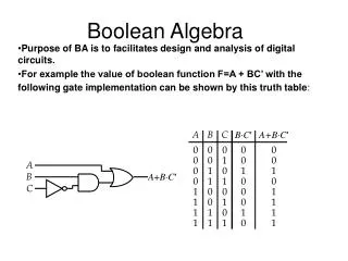
Boolean Algebra
Boolean Algebra. 1854, George Boole created a two valued algebraic system which is now called Boolean algebra . 1938, Claude Shannon adapted Boolean algebra to analyze and describe the behavior of circuits built with relays. This adaptation is called switching algebra . Switching Algebra.

Boolean Algebra
E N D
Presentation Transcript
Boolean Algebra • 1854, George Boole created a two valued algebraic system which is now called Boolean algebra. • 1938, Claude Shannon adapted Boolean algebra to analyze and describe the behavior of circuits built with relays. This adaptation is called switching algebra.
Switching Algebra • In switching algebra the condition of a logic signal is represented by symbolic variables, such as x, y, and/or z, and these variables can only have two values, 0 or 1. • Two possible conventions: • Positive Logic. • Where LOW = 0 and HIGH = 1. • Negative Logic. • Where LOW = 1 and HIGH =0.
Axioms • The axioms or postulates of a mathematical system are a minimum set of basic definitions that are assumed to be true, and from which all other information about the system can be derived. • The axioms stated below embody the “digital abstraction” by formally stating that X can take on only one of two values. • (A1) X = 0 if X 1 • (A1’) X = 1 if X 0
Axioms • Complement. • (A2) If X = 0, then X’ = 1. • (A2’) If X = 1, then X’ = 0. • Notation.
Axioms • Logical multiplication ( ). • (A3) 0 0 = 0 • (A4) 1 1 = 1 • (A5) 0 1 = 1 0 = 0 • Logical addition ( + ). • (A3’) 1 + 1 = 1 • (A4’) 0 + 0 = 0 • (A5’) 1 + 0 = 0 + 1 = 1
Precedence • By convention, the precedence of operations in a logic expression is the following: • Parentheses. • Complement. • Multiplication. • Addition.
Theorems • Theorems are statements, known to be always true, that are used to manipulate algebraic expressions to allow simpler analysis or more efficient synthesis of circuits. • Identities. • (T1) X + 0 = X • (T1’) X 1 = X • Null elements. • (T2) X + 1 = 1 • (T2’) X 0 = 0 • Idempotency. • (T3) X + X = X • (T3’) X X = X
Theorems • Involution. • (T4) (X’)’ = X • Complements. • (T5) X + X’ = 1 • (T5’) X X’ = 0 • Proofs. • Theorems T1 through T5’ can be proved by using a technique called perfect induction. • Since a switching variable can take on only two different values, 0 or 1 by Axiom A1, we can prove a theorem involving a single variable by showing that the theorem is true for both X=0 and X=1.
Theorems • Proof of theorem (T2). X + 1 = 1 • Two cases: • X = 0 • 0 + 1 = 1 is true according to A5’. • X = 1 • 1 + 1 = 1 is true according to A3’.
Theorems • Commutativity. • (T6) X + Y = Y + X • (T6’) X Y = Y X • Associativity. • (T7) (X + Y) + Z = X + (Y + Z) • (T7’) (X Y) Z = X (Y Z) • Distributivity. • (T8) X Y + X Z = X (Y + Z) • (T8’) (X + Y) (X + Z) = X + Y Z • Comments. • Ambiguity of X+Y+W+Z from a strictly algebraic point of view. • Proofs, same as before, perfect induction.
Theorems • Covering (absorption). • (T9) X + X Y = X • (T9’) X (X + Y) = X • Combining. • (T10) X Y + X Y’ = X • (T10’) (X + Y) (X + Y’) = X • Consensus. • (T11) X Y + X’ Z + Y Z = X Y + X’ Z • (T11’) (X + Y) (X’ + Z) (Y + Z) = (X + Y) (X’ + Z) • Comments. • T9 and T10 are used in minimization of logic functions. • T10 used to eliminate timing hazards and to find prime implicants (iterative consensus method).
Theorems • Proof of theorem (T9). X + X Y = X (T1’) X 1 + X Y = X (T8) X (1 + Y) = X (T2) X 1 = X (T1’) X = X • Proof of theorem (T10). X Y + X Y’ = X (T8) X (Y + Y’) = X (T5) X 1 = X (T1’) X = X
Theorems • Any expression can be substituted for X, Y and Z in the previous theorem. • For example: Simplify W = A’BC + A’. Substitute X = A’ and Y = BC. W = XY + X According to theorem (T9) XY + X = X Therefore W = X = A’
Theorems • Simplify: W = [A + B’C + DEF] [A + B’C + (DEF)’] Substitute X = A + B’C and Y = DEF W = [X + Y] [X + Y’] According to theorem (T10’) [X + Y] [X + Y’] = X Therefore W = X = A + B’C
Theorems • Generalized Idempotency. • (T12) X + X + … + X = X • (T12’) X X … X = X • DeMorgan’s Theorem. • (T13) (X1 X2 … Xn)’ = X1’ + X2’ + … + Xn’ • (T13’) (X1 + X2 + … + Xn)’ = X1’ X2’ … Xn’
Theorems • Generalized DeMorgan’s Theorem. • (T14) [F(X1 , X2 , … , Xn,+,)]’ = [F(X1’, X2’, … , Xn’,,+)] • Example: • (X Y + W Z)’ = (X’ + Y’) (W’ + Z’) • Shannon’s Expansion Theorem. • (T15) F(X1,X2, … ,Xn) = X1 F(1,X2, … ,Xn) + X1’ F(0,X2, … ,Xn) • (T15’) F(X1,X2, … ,Xn) = X1 + F(0,X2, … ,Xn) X1’ + F(1,X2, … ,Xn)
Theorems • The theorems with n variables can be proved with the finite induction technique. With finite induction, first you prove that the theorem is true for the case where n = 2 (basis step), then you prove that if the theorem is true for n = i, then it is also true for n = i + 1 (induction step).
Theorems • Ex: Prove theorem (T12) X + X + … + X = X • Basis step. X + X= X true by (T3). • Induction step. X + X + X = X (X + X) + X = X (X) + X = X X = X + X + X
Principle of Duality • Every algebraic expression deducible from the postulates of Boolean Algebra remains valid if the operators and identity elements are interchanged. • Ex: • X + X Y = X • X (X + Y) = X • Do not do this: • X + X Y = X • X X + Y = X • X + Y = X
Principle of Duality • Formal definition: • FD(X1 , X2 , … , Xn,+,,’) = F(X1, X2 , … , Xn,,+,’)
Standard Representation of Logic Functions • Truth table is a table of all possible combinations of the variables showing the relationship between the values that the variables may take and the result of the operation.
Standard Representation of Logic Functions • Literal is a primed or unprimed variable. • X, X’ • Product Term is a single literal or the logical product of two or more literals. • X, X Y, X’ Y Z • Sum of Products Expression is a logical sum of product terms. • X’ + W Y + X Y Z
Standard Representation of Logic Functions • Sum Term is a single literal or the logical sum of two or more literals. • X, X’ + Y, X + Y’ + Z’ • Product of Sums Expression is a logical product of sum terms. • X (W + Y) ( X’ + Y + Z) • Normal Term is a product or sum term in which a variableappears only once. • X’ Y Z, X + Y’ + Z’ (normal terms) • X’ Y Y Z, X + X + Y’ + Z’ (non-normal terms)
Standard Representation of Logic Functions • n-Variable Minterm is a normal product term with n literals. • For n = 3 • X’ Y Z • n-Variable Maxterm is a normal sum term with n literals. • For n = 4 • W’ + X + Y’ + Z
Standard Representation of Logic Functions • Minterm number is a n-bit integer used to represent a minterm. • Maxterm number is a n-bit integer used to represent a maxterm.
Standard Representation of Logic Functions • Canonical Sum is a sum of minterms corresponding to truth table rows for which the function produces a 1, also known as the on-set. • F = X,Y,Z(1,4,7) • F = X’Y’Z + XY’Z’ + XYZ • Canonical Product is the product of maxterms corresponding to truth table rows for which the function produces a 0, also known as the off-set. • F = X,Y,Z(1,2) • F = (X + Y + Z’) (X + Y’ + Z)
Standard Representation of Logic Functions • It is easy to convert from a minterm list to a maxterm list and vice versa. • For a function of n variables, the possible minterm and maxterm numbers are in the set {0,…,2n – 1}. • A minterm or maxterm list is a subset of these numbers. Therefore to switch between list types, take the set complement.
Standard Representation of Logic Functions • Ex: • X,Y,Z(1,4,7) = X,Y,Z(0,2,3,5,6,) • X,Y(1,2) = X,Y(0,3)
Combinational Circuit Analysis and Synthesis • Analysis: • Given a logic diagram: • Find out what the circuit does. • Find out it’s boolean function. • Obtain a formal description of the circuit’s logic function. • Synthesis: • Given a problem statement: • Design the circuit. • Obtain the logic diagram.
Combinational Circuit Analysis • Use basic axioms of switching algebra to derive the truth table for the circuit under analysis. • Truth table would be the final result. • Number of input combinations grows exponentially.
Combinational Circuit Analysis • Start at the inputs and propagate expressions through the gates towards the output. • F = ((X+Y’)Z)+(X’YZ’)
Combinational Circuit Analysis • Sum of products form. • F = ((X + Y’) Z) + (X’YZ’) • Multiply out. • F = XZ + Y’Z + X’YZ’
Combinational Circuit Analysis • Product of sums form. • F=((X+Y’)Z)+(X’YZ’) • Add out. • F=(X+Y’+X’)(X+Y’+Y)(X+Y’+Z’) (Z+X’)(Z+Y)(Z+Z’) • F=(X+Y’+Z’)(Z+X’)(Z+Y)
Combinational Circuit Analysis • Using DeMorgan’s Theorem to simplify circuits with NAND and NOR gates. • F=[((WX’)’Y)’+(W’+X+Y’)’+(W+Z)’]’ • F=((W’+X)’+Y’)’(WX’Y)’(W’Z’)’ • F=((WX’)’Y)(W’+X+Y’)(W+Z) • F=((W’+X)Y)(W’+X+Y’)(W+Z)
Combinational Circuit Analysis • F=[((WX’)’Y)’+(W’+X+Y’)’+(W+Z)’]’ • F=((W’+X)’+Y’)’(WX’Y)’(W’Z’)’ • F=((WX’)’Y)(W’+X+Y’)(W+Z) • F=((W’+X)Y)(W’+X+Y’)(W+Z)
Exclusive-OR Gate • An exclusive-OR gate is a two input device whose output is 1 if exactly one of its inputs is 1. • Also known as an XOR gate. • F=X’Y+XY’=XY
Combinational Circuit Synthesis • The problem is stated. • The number of input and output variables is determined and variable names are assigned to them. • The truth table that defines the required relationship between inputs and outputs is derived. • The simplified Boolean function for each output is obtained. • Logic diagram is drawn.
Combinational Circuit Synthesis • Design a circuit to convert a 3 bit binary number into a 3 bit gray code number. • 3 inputs labeled A, B, and C. • 3 outputs labeled X, Y, and Z.
Combinational Circuit Synthesis • X=AB’C’+AB’C+ABC’+ABC • X=A(B’C’+B’C+BC’+BC) • X=A • Y=A’BC’+A’BC+AB’C’+AB’C • Y=A’B(C’+C)+AB’(C’+C) • Y=A’B+AB’=AB • Z=A’B’C+A’BC’+AB’C+ABC’ • Z=B’C(A’+A)+BC’(A’+A) • Z=B’C+BC’= BC
Combinational Circuit Synthesis • X=A • Y=A’B+AB’=AB • Z=B’C+BC’= BC
Circuit Manipulations • Design methods described so far use AND, OR and NOT gates. • NAND and NOR gates are faster in most technologies than AND and OR gates. • Most people do not develop logical propositions in terms of NAND and NOR connectives. • Bubble to bubble design.
Circuit Minimization • Canonical sum of products and canonical product of sums are uneconomical to realize. • Number of minterms and maxterms grows exponentially with the number of input variables. • What can be done to minimize logic functions: • Minimize number of 1st level gates. • Minimize number of inputs on each 1st level gate. • Minimize number of inputs on 2nd level gate. • Methods are based on theorem T10 and T10’. • XY + XY’ = X and (X+Y)(X+Y’)=X
Circuit Minimization • Prime number detector. • 4 inputs - N3, N2, N1, and N0 • 1 output – F
Circuit Minimization • Consider the minterms numbers 1, 3, 5, and 7 of the prime number detector logic function derived earlier. • G=N3’N2’N1’N0+N3’N2’N1N0+ N3’N2N1’N0+ N3’N2N1N0 • G=N3’N2’N0(N1’+N1)+ N3’N2N0 (N1’+N1) • G=N3’N2’N0+N3’N2N0 • G=N3’N0(N2’+N2) • G=N3’N0
Circuit Minimization • G=N3’N0
Karnaugh Maps • Graphical representation of a logical function’s truth table. • The map for an n-input logic function is an array with 2n cells. • The small numbers inside the each cell are the corresponding minterm numbers in the truth table. Truth table inputs are labeled from left to right ( e.g. X, Y, Z).