Download
1 / 28
370 likes | 727 Vues
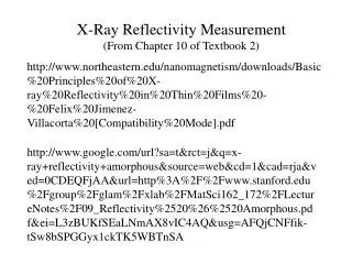
X-Ray Reflectivity Measurement (From Chapter 10 of Textbook 2). http://www.northeastern.edu/nanomagnetism/downloads/Basic%20Principles%20of%20X-ray%20Reflectivity%20in%20Thin%20Films%20-%20Felix%20Jimenez-Villacorta%20[Compatibility%20Mode].pdf.

E N D
X-Ray Reflectivity Measurement (From Chapter 10 of Textbook 2) http://www.northeastern.edu/nanomagnetism/downloads/Basic%20Principles%20of%20X-ray%20Reflectivity%20in%20Thin%20Films%20-%20Felix%20Jimenez-Villacorta%20[Compatibility%20Mode].pdf http://www.google.com/url?sa=t&rct=j&q=x-ray+reflectivity+amorphous&source=web&cd=1&cad=rja&ved=0CDEQFjAA&url=http%3A%2F%2Fwww.stanford.edu%2Fgroup%2Fglam%2Fxlab%2FMatSci162_172%2FLectureNotes%2F09_Reflectivity%2520%26%2520Amorphous.pdf&ei=L3zBUKfSEaLNmAX8vIC4AQ&usg=AFQjCNFfik-tSw8bSPGGyx1ckTK5WBTnSA
X-ray is another light source to be used to perform reflectivity measurements. Refractive index of materials (: X-ray): re: classical electron radius = 2.818 × 10⁻¹⁵ m-1 e: electron density of the materials x: absorption coefficient
1 Definition in typical optics: n1sin1 = n2sin2 In X-ray optics: n1cos1 = n2cos2 > 1 n <1, 2
Critical angle for total reflection n1cos1 = n2cos2, n1= 1; n2=1- ; 1 = c; 2 = 0 cosc=1- sinc= and c <<1 ~ 10-5 – 10-6; and c ~ 0.1o – 0.5o 1 c 1-
X-ray reflectivity from thin films: Single layer: Path difference = BCD
Snell’s law in X-ray optics: n1cos1 = n2cos2 cos1 = n2cos2=(1-)cos2. 1- 2 cos1 When 1 , 2, and << 1 Ignore Constructive interference:
Si on Ta Slope = a /180 b use So that the horizontal axis is linear
Fresnelreflectivity: classical problem of reflection of an EM wave at an interface – continuity of electric field and magnetic field at the interface Refracted beam Reflected beam k3 3 Reflection and Refraction: • Random polarized beam travel in two homogeneous, isotropic, nondispersive, and nonmagnetic media (n1 and n2). Snell’s law: k2 x 2 Incident beam k1 1 y n1 n2 and Continuity can be written for two different cases: (a) TE (transverse electric) polarization: electric field is to the plane of incidence.
E3x E1x E1 E3 1 3 H1y H3y E2x H2y E2 2 (horizontal field) (scalar) &
(b) TM (transverse magnetic) polarization: magnetic field is to the plane of incidence. E1y E3y E1 E3 1 3 H1x H3x E2y H2x E2 2
http://en.wikipedia.org/wiki/Image:Fresnel2.png Rs: s-polarization; TE mode Rp: p-polarization; TM mode Another good reference (chapter 7) http://www.ece.rutgers.edu/~orfanidi/ewa/
In X-ray arrangement n1 = 1, change cos sin 1 2 cos1/n2 all angles are small; sin1 ~ 1. Snell’s law obey cos1 = n2 cos2.
in term of Effect of surface roughness is similar to Debye-Waller factor The result can be extended to multilayer. The treatment is the same as usual optics except definition of geometry!
One can see that the roughness plays a major role at high wave vector transfers and that the power law regime differs from the Fresnel reflectivity at low wave vector transfers
X-ray reflection for multilayers L. G. Parratt, “Surface studies of solids by total reflection of x-rays”, Phys. Rev. 95 359 (1954). y z Electric vector of the incident beam: Reflected beam: Refracted beam:
Boundary conditions for the wave vector at the interface between two media: frequencies must be equal on either side of the interface: 1 = 2 , n1 1= n22 n2k1 = n1k2; wave vector components parallel to the interface are equal
From first boundary condition From second boundary condition
Shape of reflection curve: two media The Fresnel coefficient for reflection Page 10 A, B are real value
From Snell’s law Page 4
N layers of homogeneous media Thickness of nth layer: medium 1: air or vacuum an : the amplitude factor for half the perpendicular depth n-1 0 n
The continuity of the tangential components of the electric vectors for the n-1, n boundary (1) The continuity of the tangential components of the magnetic field for the n-1, n boundary (2) Solve (1) and (2); (1)fn-1+(2), (1)fn-1-(2)
For N layers, starting at the bottom medium (N+1 layer: substrate) Also, a1 = 1 (air or vacuum) Finally, the reflectivity of the system is For rough interfaces: Can be calculated numerically!
Example of two layers with roughness Au on Si substrate
Interface roughness z Probability density Integration Refractive index Same roughness & refractive index profile