Download

1 / 43
550 likes | 1.67k Vues
Different optical phenomena and their applications

E N D
DR.RABIUL HUSSAIN SCHOOL OF MSE, JIMMA INSTITUTE OF TECHNOLOGY JIMMA UNIVERSITY,ETHIOPIA OPTICAL PROPERTIES
INTRODUCTION • Engineering materials are important in everyday life because of their versatile structural properties. • Other than these properties , they do play an important role because of their physical properties. • Prime physical properties of materials include : electrical properties ; thermal properties ; magnetic properties ; and optical properties. • The optical properties of engineering materials are useful in different applications . • Ex.: domestic , medicine , astronomy , manufacturing.
introduction • Optical property of a material is defined as its interaction with electro-magnetic radiation in the visible region. • Electromagnetic spectrum of radiation spans the wide range from γ-rays with wavelength as 10-12 m , through x-rays , ultraviolet , visible , infrared , and finally radio waves with wavelengths as long as 105m. • Visible light is one form of electromagnetic radiation with wavelengths ranging from 0.39 to 0.77 μm. • Light can be considered as having waves and consisting of particles called photons. E = h = h c/
ELECTROMAGNETIC RADIATION • When electrically charged particles moves under acceleration, accelerating electrical and magnetic fields are produced which are perpendicular to each other. These fields are transmitted in the form of waves called electromagnetic waves or electromagnetic radiation. • Light waves are also associated with oscillating electric and magnetic field. DR.RABIUL HUSSAIN/966882081
Properties of Electromagnetic Radiation • Energy travels in space in the form of electromagnetic radiation. The oscillating electric and magnetic field associated are perpendicular to each other and to the direction of wave. • Unlike sound waves or water waves, electromagnetic waves do not require any medium and can move in vacuum. • There are many types of electromagnetic radiations, which differ from one another in wavelength, (or frequency,). This constitute what is called electromagnetic spectrum. DR.RABIUL HUSSAIN/966882081
Electromagnetic radiation DR.RABIUL HUSSAIN/966882081
ELECTROMAGNETIC RADIATION SPECTRUM DR.RABIUL HUSSAIN/966882081
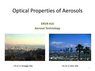
VISIBLE LIGHT • Light from the sun is essential for life on earth. • It must be remember that visible light is just a small portion of the electromagnetic radiation. • Visible light (white light) consists of different colors-each having different wavelengths and frequency. DR.RABIUL HUSSAIN/966882081
Important terminology • Intensity (I): The term intensity is used to describe the rate at which light spreads over a surface of a given area some distance from a source. The intensity varies with the distance from the source and the power of the source. Intensity is like brightness, and is measured as the rate at which light energy is delivered to a unit of surface, or energy per unit time per unit area. • Power (P)is a property of the light source that describes the rate at which light energy is emitted by the source. Power is often expressed in units of watts. • Different light bulbs are rated to have different power values. Typically, the purpose of a light determines what power bulb will be used in the light. Table 2 shows the dependence of intensity (I) at a distance of 1.0 meter from various types of light bulbs.
Material – light interaction • Interaction of photons with the electronic or crystal structure of a material leads to a number of phenomena. • The photons may give their energy to the material (absorption); photons give their energy, but photons of identical energy are immediately emitted by the material (reflection); photons may not interact with the material structure (transmission); or during transmission photons are changes in velocity (refraction). • At any instance of light interaction with a material, the total intensity of the incident light striking a surface is equal to sum of the absorbed, reflected, and transmitted intensities i.e.
MATERIAL-LIGHT INTERACTION • An alternate equation is: T + A + R = 1 where T, A, and R represent, respectively, the transmissivity (IT/I0), absorptivity (IA/I0), and reflectivity (IR/I0), or the fractions of incident light that are transmitted, absorbed, and reflected by a material; their sum must equal unity because all the incident light is transmitted, absorbed, or reflected.
Optical materials • Materials are classified on the basis of their interaction with visible light into three categories. • Materials that are capable of transmitting light with relatively little absorption and reflection are called transparent materials i.e. we can see through them. • Translucent materials are those through which light is transmitted diffusely i.e. objects are not clearly distinguishable when viewed through. • Those materials that are impervious to the transmission of visible light are termed as opaque materials . These materials absorb all the energy from the light photons.
Optical properties of metals • Metals consist partially filled high-energy conduction bands . • When photons are directed at metals , their energy is used to excite electrons into unoccupied states . Thus metals are opaque to the visible light . • Metals are , however , transparent to high end frequencies i.e. x-rays and γ- rays . • Absorption of takes place in very thin outer layer . Thus , metallic films thinner than 0.1 μm can transmit the light. • The absorbed radiation is emitted from the metallic surface in the form of visible light of the same wavelength as reflected light . The reflectivity of metals is about 0.95
Optical properties of metals • When visible light in directed on a metal surface, the energy is used to excite electrons into unoccupied energy states above the Fermi level, thus making metals behave as opaque materials i.e. light is absorbed. • Most of the absorbed radiation is emitted from the metallic surface in the form of visible light of the same wavelength as reflected light. • The amount of energy absorbed by metals depends on the electronic structure of each particular metal.
Optical properties of non-metals • Non-metallic materials consist of various energy band structures. Thus, all four optical phenomena are important. • Refraction: when light photons are transmitted through a material, they causes polarization of the electrons and in-turn the speed of light is reduced and the beam of light changes direction. • Refractive index, n= C0/C where c0– speed of light in vacuum, c – speed of light in the concerned material
refraction • Speed of light can be related to its electrical and magnetic properties as • Where r and µr are the dielectric constant and the relative magnetic permeability, respectively. • Since most materials are only slightly magnetic: Thus, for transparent materials, index of refraction and dielectric constant are related.
refraction Snell’s Law of Refraction: Refractive indices for light passing through from one medium with refractive index n through another of refractive index nis related to the incident angle, θ, and refractive angle, θ, by the following relation: • If light passes from a medium with a high refractive index to one with a low refractive index, there is a critical angle of incidence, θc, which if increased will result in total internal reflection of the light. This angle is defined as θ’ (refraction) = 90°.
REFLECTION: • When light radiation passes from one medium into another having a different index of refraction, some of the light is scattered at the interface between the two media, even if both are transparent. The reflectivity R represents the fraction of the incident light that is reflected at the interface, or R =IR/I0 • If the light is normal (or perpendicular) to the interface, then • If the incident light is not normal to the interface, R depends on the angle of incidence. When light is transmitted from a vacuum or air into a solid s, then
REFLECTION • Materials with a high index of refraction have a higher reflectivity than materials with a low index . Because the index of refraction varies with the wavelength of the photons , so does the reflectivity. • In metals , the reflectivity is typically on the order of 0.90-0.95 , whereas for glasses it is close to 0.05 . The high reflectivity of metals is one reason that they are opaque . High reflectivity is desired in many applications including mirrors , coatings on glasses , etc.
ABSORPTION • When a light beam in impinged on a material surface , portion of the incident beam that is not reflected by the material is either absorbed or transmitted through the material. • Bouguer’s law : The fraction of beam that is absorbed is related to the thickness of the materials and the manner in which the photons interact with the material’s structure. • where I – intensity of the beam coming out of the material, I0 – intensity of the incident beam, x – path through which the photons move, and α – linear absorption coefficient, which is characteristic of a particular material. • Absorption occurs by two mechanisms : Rayleigh scattering and Compton scattering.
ABSORPTION MECHANISMS • Rayleigh scattering : where photon interacts with the electrons , it is deflected without any change in its energy . This is significant for high atomic number atoms and low photon energies . Ex.: Blue color in the sunlight gets scattered more than other colors in the visible spectrum and thus making sky look blue. • Tyndall effect is where scattering occurs from particles much larger than the wavelength of light . Ex. : Clouds look white. • Compton scattering –interacting photon knocks out an electron loosing some of its energy during the process . This is also significant for high atomic number atoms and low photon energies. • Photoelectric effect occurs when photon energy is consumed to release an electron from atom nucleus . This effect arises from the fact that the potential energy barrier for electrons is finite at the surface of the metal . Ex. : Solar cells.
TRANSMISSION • The fraction of beam that is not reflected or absorbed is transmitted through the material. Thus the fraction of light that is transmitted through a transparent material depends on the losses incurred by absorption and reflection:
APPLICATIONS OF OPTICAL PHENOMENA • Light interacts with a material in many ways. • Depending on the material , its crystal- / micro- structure ,and also on the characteristics of incident light , there are many peculiar phenomena occurs , which are known as optical phenomena . These include : • Luminescence • Lasers • Thermal emission • Photo-conductivity • Optical fibers • All these find quite many applications in technology for everyday life.
Application 1: luminescence • It is the process where a material absorbs energy and then immediately emits visible or near-visible radiation . It consists of electron excitation and then dropping down to lower energy states . • If the emission of radiation occurs within 10-8 sec. s after excitation , the luminescence is called fluorescence , and if it takes longer than 10-8sec.s, it is known as phosphorescence. • Ordinarily pure materials do not display this phenomenon . Special materials called phosphors have the capability of absorbing high- energy radiation and spontaneously emitting lower – energy radiation . Ex. : some sulfides , oxides , tungstates , and few organic materials .
luminescence • The intensity of luminescence is given as: • where I0– initial intensity of luminescence, • I – fraction of luminescence after time, t, • T - relaxation time, constant for a material. • Luminescence process is classified based on the energy source for electron excitation as photo-luminescence, cathode-luminescence, and electro-luminescence.
PHOTOLUMINESCENCE • Photo-luminescence occurs in fluorescent lamps. • Here ultra-violet radiation from low-pressure mercury arc is converted to visible light by calcium halo-phosphate phosphor (Ca10F2P6O24). • In commercial lamps, about 20% of F- ions are replaced with Cl- ions. • Antimony, Sb3+, ions provide a blue emission while manganese, Mn2+, ions provide an orange-red emission band.
CATHODE LUMINESCENCE • Cathode-luminescence is produced by an energized cathode which generates a beam of high-energy bombarding electrons. • Applications of this include electron microscope; cathode-ray oscilloscope; color television screens. • The modern televisions have very narrow, about 0.25 mm wide, vertical stripes of red-, green-, and blue- emitting phosphors deposited on the inner surface of the screens. • Commercial phosphors for different colors are: red – yttrium oxy-sulfide (Y2O2S) with 3% europium (Eu); green – (Zn,Cd)S with a Cu+ acceptor and Al3+ donor; blue – zinc sulfide (ZnS) with Ag+ acceptor and Cl- donor.
ELECTROLUMINESCENCE • Electro-luminescence occurs in devices with p-n rectifying junctions which are stimulated by an externally applied voltage. • When a forward biased voltage is applied across the device, electrons and holes recombine at the junction and emit photons in the visible range (mono-chromatic light i.e. singe color). These diodes are called light emitting diodes (LEDs). • LEDs emit light of many colors, from red to violet, depending on the composition of the semiconductor material used. • Ex.: GaAs, GaP, GaAlAs, and GaAsP are typical materials for LEDs.
APPLICATION 2: LASER • Laser is an acronym for light amplification by stimulated emission of radiation. It is in fact special application of luminescence. • Unlike most radiation processes, such as luminescence, which produce incoherent light, the light produced by laser emission is coherent. • This is based on the fact that in certain materials, electrons excited by a stimulus produce photons which in turn excite additional photons of identical wavelength. Thus a large amplification of the photons emitted in the material occurs. • Lasers are useful in many applications such as welding, metal cutting, heat treatment, surgery, mapping, reading compact disks, etc. Ex.: Ruby, single crystal of Al2O3 doped with little amount of Cr2O3; yttrium aluminium garnet (Y3Al5O12– YAG) doped with neodymium, Nd; CO2gas; He-Ne gas; some semi-conductors like GaAs and InGaAsP.
APPLICATION 3: THERMAL EMISSION • When a material is heated, electrons are excited to higher energy levels, particularly in the outer energy levels where the electrons are less strongly bound to the nucleus. • These excited electrons, upon dropping back to the ground state, release photons in process what is called thermal emission. • During thermal emission a continuous spectrum of radiation is emitted with a minimum wavelength and the intensity distribution is dependent on the temperature. • Higher the temperature, wider will be the range of wavelengths emitted. By measuring the intensity of a narrow band of the emitted wavelengths with a pyrometer, material’s temperature can be estimated.
APPLICATION 4: PHOTOCONDUCTIVITY • Bombardment of semiconductors by photons, with energy equal to greater than the band gap, may result in creation of electron-hole pairs that can be used to generate current. This process is called photo-conductivity. • It is different from photo-electric effect in the sense that an electron-hole pair is generated whose energy is related to the band gap energy instead of free electron alone whose energy is related to the Fermi level. • The current produced in photo-conductivity is directly related to the incident light intensity. • This phenomenon is utilized in photographic light meters. Cadmium sulfide (CdS) is commonly used for the detection of visible light, as in light meters. • Photo-conductivity is also the underlying principle of the photo-voltaic cell, known to common man as solar cell, used for conversion of solar energy into electricity.
APPLICATION 5: OPTICAL FIBERS • Optical fibers have revolutionized the communication industry. • These systems consists of transmitter (a semiconductor laser) to convert electrical signals to light signals, optical fiber to transmit the light signals, and a photodiode to convert light signals back to electrical signals. • It primarily consists of core, cladding and coating. The core transmits the signals, while the cladding constrains the light beam to the core; outer coating protects the core and cladding from the external environment. • Typically both the core and cladding are made of special types of glass with carefully controlled indices of refraction. • The indices of refraction are selected such that ncladding < ncore
OPTICAL FIBERS • Once the light enters the core from the source, it is reflected internally and propagates along the length of the fiber. • Internal reflection is accomplished by varying the index of refraction of the core and cladding glass materials. Usually two designs are employed in this regard.
Types of optical fibers • In step-index optical fiber, there is a sharp change in refractive index between the core and cladding. In this design output pulse will be broader than the input one. It is because light rays traveling in different trajectories have a variety of path lengths. • It is possible to avoid pulse broadening by using graded-index fiber. This results in a helical path for the light rays, as opposed to zig-zag path in a step-index fiber. • Here impurities such as boron oxide (B2O3) or germanium dioxide (GeO2) are added to the silica glass such that the index of refraction varied gradually in parabolic manner across the cross section. This enables light to travel faster while close to the periphery than at the center. This avoids pulse broadening. • Both step- and graded- index fibers are termed as multi-mode fibers. • Third type optical fiber is called single-mode fiber in which light travels largely parallel to the fiber axis with little distortion of the digital light pulse. These are used for long transmission lines.
OPTICAL FIBER PROPERTIES • Core and cladding materials are selected not only on the basis of their refractive indices, but also on basis of ease of manufacturability, light loss, mechanical strength properties and dispersion properties. • However, density (ρ) and refractive index (n) are critical. These two parameters are related approximately as • High-purity silica-based glasses are used as fiber material, with fiber diameter ranging from 5 to 100 μm. • The fibers are carefully fabricated to be virtually free from flaws.
THANK YOU VERY MUCH IT WAS NICE BEING WITH YOU