

interaction diagram
E N D
Presentation Transcript
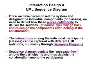
Engineering Technical college-ErbilDep. of ISE Software Construction Lecture Slides #5: Interaction UML models S1 2014 Asst.Prof.Dr.Raghad Z.Yousif
Dynamic Modeling with UML • Diagrams for dynamic modeling • Interaction diagrams describe the dynamic behavior between objects • Statecharts describe the dynamic behavior of a single object
Dynamic Modeling with UML • Interaction diagrams • Sequence Diagram: • Dynamic behavior of a set of objects arranged in time sequence, new objects added to the right • Good for real-time specifications and complex scenarios • Derived from use case scenario • Collaboration Diagram : • Shows the relationship among objects. Does not show time • Objects are arranged in a graph or network format
Sequence Diagrams vs Collaboration Diagrams • Sequence diagram :ClassA :ClassB message2() message1() message3()
Sequence Diagrams vs Collaboration Diagrams • Collaboration diagram message1() :ClassA 1. message2() 2. message3() :ClassB
Sequence Diagrams vs Collaboration Diagrams • Sequence diagrams : • Strength: clearly show sequence or time ordering of events, simple notation • Weakness: forced to extend to the right when adding new objects • Collaboration diagrams : • Strength: space economical flexibility to add new objects in two dimensions, better to illustrate complex branching, iteration and concurrent behavior • Weakness: difficult to see sequence of messages, more complex notation
Dynamic Modeling with UML • State Chart Diagram: • A state machine that describes the response of an object of a given class to the receipt of outside stimuli (Events). • Activity Diagram: • Special type of statechart where all states are action states
State Chart Diagram vs Sequence Diagram • State chart diagrams help to identify: • Changes to objects over time • Sequence diagrams help to identify • The temporal relationship between objects over time • Sequence of operations as a response to one ore more events
Dynamic Modeling • Definition of dynamic model: • A collection of multiple state chart diagrams, one state chart diagram for each class with important dynamic behavior. • Purpose: • Detect and supply methods for the object model • How do we do this? • Start with use case or scenario • Model interaction between objects => sequence diagram • Model dynamic behavior of single objects => statechart diagram
Start with Flow of Events from Use Case • Flow of events from “Process Sale” Use case: • 1. Customer arrives at POS checkout with goods and/or services • 2. Cashier starts new sale • 3. Cashier enters item identifier • 4. System records sale line item and presents item description, price and running total. Cashier repeats steps 3-4 until indicates done • 5. System presents total with taxes calculated • 6. Cashier tells customer the total and asks for payment • 7. Customer pays and system handles payment
What is an Event? • Something that happens at a point in time • Relation of events to each other: • Causally related: Before, after, • Causally unrelated: concurrent • An event sends information from one object to another • One distinguishes between • The instance of an event : enterItem • The attributes of an event : itemID, quantity
Sequence Diagrams • From the flow of events in the use case or scenario proceed to the sequence diagram • A sequence diagram is a graphical description of objects participating in a use case or scenario. • Relation to object identification: • Objects/classes have already been identified during object modeling • Objects are identified as a result of dynamic modeling • Heuristic: • An event always has a sender and a receiver. Find them for each event => These are the objects participating in the use case
Sequence Diagrams • Use cases and participating objects are found. What now? • Sequence diagram - A diagram that shows object interactions arranged in time sequence for a specific use case or scenario. • A sequence diagram includes time but does not include object relationships. • A sequence diagram is useful to model a use case or scenario with its participating objects. It often leads to the detection of new participating objects.
Drawing Sequence Diagrams • Each column represents an object that is participating in the interaction. • The vertical axis represents time (from top to bottom). Messages are shown by full arrows. • Labels on full arrows represent message names and arguments. • Activations (i.e., the time it takes to perform an operation) are depicted by a rectangle attached to an object. The height of the rectangle is indicative for the duration of the operation • The vertical rectangle shows that an object is active, that is, it is handling a request made by another object. • The operation can itself send other requests to other objects • An object can request an operation from itself (looping arrow)
Sequence Diagrams :Cashier : System makenewSale() enterItem(itemID, quantity) description, total endSale() total makePayment(amount) change due, receipt
Sequence Diagrams Iterations • may have square brackets containing a continuation condition (until) specifying the condition that must be satisfied in order to exit the iteration and continue with the sequence • may have an asterisk followed by square brackets containing an iteration (while or for) expression specifying the number of iterations
Sequence Diagrams • Iteration in sequence diagrams is denoted by a box with an associated iteration expression. :Cashier : System makenewSale() enterItem(itemID, quantity) description, total *[more items]
Sequence Diagrams • Iteration in sequence diagrams is denoted by a box with an associated continuation expression. :Cashier : System makenewSale() enterItem(itemID, quantity) description, total [no more items]
Sequence Diagrams • Naming objects • Class name only :Classname • Instance name only objectName • Instance name and class name together object:Class • Most of the time you use the class name, but if you refer to a particular instance in a scenario the object:Class notation is used. • A scenario is an instance of a use case, where we take real or hypothetical people and things and follow them through the steps of the use case.
Sequence Diagrams • Conditional messages: A message might contain a guard condition denoted in square brackets obj1:Class obj2: Class message() [x < 15] calculate()
Sequence Diagrams • Sequence diagrams may contain branches. Branching involves multiple messages originating at the same time from a single class role. • The branch represents conditionality if the guard conditions on all the branches are mutually exclusive. Thus, only one message is sent. • The branch represents concurrency if the guard conditions are mutually inclusive. Thus multiple messages are sent.
Sequence Diagrams • Conditionality obj1:Class obj2: Class obj3: Class [x < 15] calculate() message() [x > 20] calculate()
Sequence Diagrams • Concurrency obj1:Class obj2: Class obj3: Class calculate() message() calculate()
Sequence Diagrams • Creation and destruction of an object in sequence diagrams are denoted by the stereotypes <<create>> and <<destroy>> :Creator <<create>> : Created Object message() X <<destroy>>
Sequence Diagrams • Iteration over a Collection (multiobject) • The message is send to each element rather than repeatedly to the collection itself. :Sale :SalesLineItem t:=total() * st:=subtotal()
Collaboration Diagrams • Collaboration diagrams contain • Classes • Associations • Message exchanges within a collaboration • Collaboration diagrams describe a set of classes and associations involved in message exchange sequences, that is a collaboration among class roles and association roles, and their interactions.
Collaboration Diagrams makePayment(cash) 1: makePayment(cash) :Register :Sale 1.1 create(cash) :Payment • The first (external) message makePayment is sent to an • instance of a Register. The sender is not identified. • 2. The Register instance sends the makePaymentmessage to • to a Sale instance. • 3. The Sale instance creates an instance of a Payment.
Collaboration Diagrams • Link : A link is a connection path between two objects, it indicates some form of navigation and visibility between the objects. A link is an instance of an association. • Note that multiple messages, and messages both ways can be exchanged along the same link. 1: makePayment(cash) 2: foo() :Register :Sale 2.1: bar() link
Collaboration Diagrams • Messages : each message between objects is represented with a message expression and a small arrow indicating the direction of the message. A sequence number is added to show the sequential order of messages. 1: msg2() 2: msg3() 3: msg4() msg1() :Register :Sale 3.1: msg5()
Collaboration Diagrams • Creation of instances : the stereotype <<create>> and the property new are used to indicate the creation of new instances. <<create>> 1: make(cashier) :Register :Sale {new}
Collaboration Diagrams • Messages number sequencing : The order of messages is illustrated with sequence numbers. The numbering scheme is: • The first message is not numbered • The order and nesting of subsequent messages is shown with a legal numbering scheme, in which nested messages have a number appended to them. Nesting is denoted by prepending the incoming message number to the outgoing message number msg1() 1: msg2() :Register :Sale 1.1 msg3() :Payment
Collaboration Diagrams msg1() 1: msg2() :classA :classB 1.1 msg3() 2.1 msg5() 2: msg4() :classC 2.2: msg6() :classD
Collaboration Diagrams • Conditional Messages : A conditional message is shown by following a sequence number with a conditional clause in square brackets. msg1() 1 [color=red]: msg2() :Foo :Bar
Collaboration Diagrams Mutually exclusive messages: msg1() 1a [test]: msg2() :classA :classB 1a.1: msg3() 1b [not test]: msg4() :classC :classD 1b.1: msg5()
State Chart Diagrams • The state of an object is defined by the set of values currently held by its attributes. • At any moment in time, an object exists in a certain manner or conditon, which we say is a state. Source State Entry and Exit actions Event [Guard] / Action Target State
State Chart Diagrams • Statechart diagrams are useful when • A class has an interesting or complex life cycle, e.g. classes that create or delete instances or associations • An instance can update its attributes in a variety of ways as it goes through a life cycle. • If two classes are depending on each other, in that one of them can start the other on its life-cycle, or change the order in which it goes from state to state. • If you find that the object’s current behavior depends on what happened to it before, that is on its past history.