Interaction Diagram Notation
Interaction Diagram Notation. From Chapter 15 of Craig Larman, Applying UML and Patterns John Dalesandro. Objectives. Read basic UML Interaction (Communication and Sequence) Diagram notation. Decomposition Tools.

Interaction Diagram Notation
E N D
Presentation Transcript
Interaction Diagram Notation From Chapter 15 of Craig Larman, Applying UML and Patterns John Dalesandro
Objectives • Read basic UML Interaction (Communication and Sequence) Diagram notation
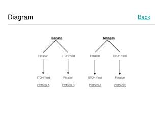
Decomposition Tools • Different styles of software development are often characterized by a strong reliance on a particular modeling tool during the design phase. • Relational Database designers tend to depend heavily on Entity Relationship Diagrams. • Functional/Procedural designers may use a tool like Function Decomposition Diagrams. • eXtreme Programming designers often use Class Responsibility Collaboration Cards.
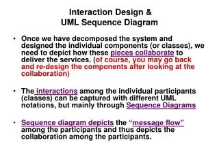
Object-Oriented Decomposition • The modeling genre of choice for most object-oriented designers is the Unified Modeling Language. • The most important activity in object-oriented design is assigning responsibility to objects. • The preferred tool to assist object-oriented designers in assigning responsibility to objects are the two UML interaction diagrams.
Introduction • Why do objects exist? • To perform an activity to help fulfill a system’s purpose • Interaction Diagrams are used to model system dynamics • How do objects change state? • How do objects interact (message passing)?
Communication & Sequence Diagrams • An Interaction Diagram is a generalization of two specialized UML diagram types • Communication Diagrams: Illustrate object interactions organized around the objects and their links to each other • Sequence Diagrams: Illustrate object interactions arranged in time sequence
Communication & Sequence Diagrams (2) • Both diagram types are semantically equivalent, however, they may not show the same information • Communication Diagrams emphasize the structural organization of objects, while Sequence Diagrams emphasize the time ordering of messages • Communication Diagrams explicitly show object linkages, while links are implied in Sequence Diagrams
Interaction Diagrams Are Valuable • Interaction Diagrams provide a thoughtful, cohesive, common starting point for inspiration during programming • Patterns, principles, and idioms can be applied to improve the quality of the Interaction Diagrams
Communication Diagrams • Objects are connected with numbered (sequenced) arrows along links to depict information flow • Arrows are drawn from the interaction source • The object pointed to by the arrow is referred to as the target • Arrows are numbered to depict their usage order within the scenario • Arrows are labeled with the passed message
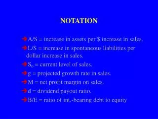
Basic Communication Diagram Notation • Link - connection path between two objects (an instance of an association) • Message - represented with a message expression on an arrowed line between objects • Sequence Number - represents the order in which the flows are used
Basic Communication Diagram Notation (2) • Conditional Message • Seq. Number [ variable = value ] : message() • Message is sent only if clause evaluates to true • Iteration (Looping) • Seq. Number * [ i := 1..N ]: message() • “*” is required; [ ... ] clause is optional
Sequence Diagrams • Correspond to one scenario within a Use Case • Model a single operation within a System over time • Identify the objects involved with each scenario • Identify the passed messages and actions that occur during a scenario • Identify the required response of each action
Basic Sequence Diagram Notation • Links - Sequence Diagrams do not show links • Message - represented with a message expression on an arrowed line between objects
Basic Sequence Diagram Notation (2) • Object Lifeline - the vertical dashed line underneath an object • Objects do not have a lifeline until they are created • The end of an object’s life is marked with an “X” at the end of the lifeline • Passage of time is from top to bottom of diagram
Basic Sequence Diagram Notation (3) • Activation - the period of time an object is handling a message (box along lifeline) • Activation boxes can be overlaid to depict an object invoking another method on itself
Basic Sequence Diagram Notation (4) • Conditional Message • [ variable = value ] message() • Message is sent only if clause evaluates to true • Iteration (Looping) • * [ i := 1..N ]: message() • “*” is required; [ ... ] clause is optional
Sequence Diagram for Java Remote Method Invocationhttp://nathanbalon.net/projects/cis578/cis578_middleware_report.pdf
Interaction Diagram Strengths • Communication Diagram • Space Economical - flexibility to add new objects in two dimensions • Better to illustrate complex branching, iteration, and concurrent behavior • Sequence Diagram • Clearly shows sequence or time ordering of messages • Simple notation
Interaction Diagram Weaknesses • Communication Diagram • Difficult to see sequence of messages • More complex notation • Sequence Diagram • Forced to extend to the right when adding new objects; consumes horizontal space
Conclusions • Beginners in UML often emphasize Class Diagrams. Interaction Diagrams usually deserve more attention. • There is no rule about which diagram to use. Both are often used to emphasize the flexibility in choice and to reinforce the logic of the operation. Some tools can convert one to the other automatically.