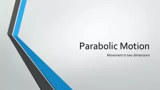
Estimation of Sound Source Direction Using Parabolic Reflection Board
210 likes | 337 Vues
This paper presents a novel technique for estimating sound source direction using a parabolic reflection board and a single microphone. It highlights the limitations of conventional microphone array methods and proposes a solution that enhances signal directionality while suppressing noise. Experimental results demonstrate that the configuration improves power gain from the intended sound source. This system can be applicable in various fields, including speech recognition and robot navigation for disaster victim search. Future work will explore optimizations and comparisons with other reflectors.

Estimation of Sound Source Direction Using Parabolic Reflection Board
E N D
Presentation Transcript
Estimation of Sound Source Direction Using Parabolic Reflection Board 2008 RISP International Workshop on Nonlinear Circuits and Signal Processing (NCSP’08) 6-8 March, 2008 Watermark Hotel, Australia Tetsuya Takiguchi, Ryoichi Takashima and Yasuo Ariki Kobe University, Japan
Table of Contents • Introduction • Purpose of Sound-source-direction Estimation • Conventional Technique • Proposed Method • Parabolic Reflection Board • Active Microphone • Experiments • Summary and Future Work
Purpose of Sound-source-direction Estimation • Noise suppression by forming directivity toward the target signal source If the system direction of the target signal source, … Noise disturb the speech recognition Noise Directivity Noise Speech
Purpose of Sound-source-direction Estimation Search robot for disaster victims Estimation of speaker for the meeting system Help !! Sound-source-direction estimation technique is necessary for various systems A is talking now.
Conventional Techniques • Microphone Arrays • Use of simultaneous phase information from microphone arrays to estimate the direction of the signal arrival. 30-channel arrays 32-channel arrays
Proposed Method Two or more microphones are necessary for conventional method It is difficult to estimateof the signal arrival using only a single microphone Goal: Sound-source-direction estimation using only a single microphone
Active microphone with Parabolic Reflector Proposed Method Diameter: 12cm Microphone Rotation manually Parabolic reflector The reflector and its associated microphone rotate together
Parabolic Reflection Board Any wave, where the sound source is located directly in front of the parabolic surface, is reflected toward the focal point. No reflection waves, where the sound source is not located directly in front of the parabolic surface,will travel toward the focal point. Focal point Focal point
Observed Signal at the Focal Point The signal is coming from directly infront of the parabolic surface s1 : Direct sound 2d s2: Reflection sound Q P s2 H Distance difference between path s1 and s2 to the focal point: QP+PO = QP+PH = 2d d : distance of the focal point s1 -d O Focal point Time difference to the focal point: a: sound speed (depending only on ‘d’) Parabolic surface Directrix Time difference for all reflection paths is equal to 2d/a.
Observed Signal at the Focal Point The signal is coming from directly in front of the parabolic surface • Observed signal at the focal point • In the frequency domain • Power spectrum Direct sound Reflection coefficient Reflection sound The use of parabolic reflector can increase the power gain of the signal arriving from the front of the parabolic reflector according to
Observed Signal at the Focal Point The sound source is not located directly in front of the parabolic surface. (Input Signal) P degrees O: Focal point Tangential line (Reflected Signal) Parabolic surface No reflection waves will travel toward the focal point!
Selection of Direction Having Maximum Power A microphone is set up at the focal point. The microphone rotates and the power of the target signal observed at each angle is calculated. The direction having maximum power is selected as the sound source direction. Rotation manually Microphone i : angle of the parabolic reflector
Experiment Conditions Parabola Reflector Target source: 90 degrees Source signal: white noise (5 sec) Microphone 30cm Loud speaker 60cm 90cm The angle of the microphone with the parabolic reflector is changed manually from 0 degrees to 180 degrees at an interval of 10 degrees.
Average Power Versus Angle of Microphone • Average log-power spectrum at 90 degrees is maximum value. • The power decreases as the direction of the microphone becomes farther • from the direction of the target sound source.
With / Without the Parabolic Reflector with reflector without reflector (The directivity of the microphone is set up opposite the sound source)
3D Power Spectrum of the Observed Signal Low-frequency: diffraction of the sound wave Power [dB] Angle of mic. [degree] Frequency [Hz] Effect is not so great for the low-frequency components of the signal. Power spectrum becomes larger as the angle of parabolic reflector is closer to 90 degrees.
Power spectrum of the signal observed without reflector The shape of the spectrum is not flat.
Summary A sound-source-direction estimation method using a single microphone only. New Proposed Method : Active microphone with parabolic reflection board is able to estimate the sound source direction using only a single microphone. In future work : research for short signal (for example, speech) form of the parabolic reflector