Lecture- 2 Fluid Statics (Part A)
Fluid Mechanics: Fundamentals of Fluid Mechanics , 7th Edition, Bruce R. Munson. Theodore H. Okiishi . Alric P. Rothmayer John Wiley & Sons, Inc.l , 2013. Lecture- 2 Fluid Statics (Part A). Lecture slides by Dhafer Manea Hachim 2016-2017

Lecture- 2 Fluid Statics (Part A)
E N D
Presentation Transcript
Fluid Mechanics: Fundamentals of Fluid Mechanics, 7th Edition, Bruce R. Munson. Theodore H. Okiishi. Alric P. Rothmayer John Wiley & Sons, Inc.l, 2013 Lecture- 2Fluid Statics (Part A) Lecture slides by Dhafer Manea Hachim 2016-2017 Department of Automotive Technical Engineering
Learning Objectives • After completing this Lecture, you should be able to: • determine the pressure at various locations in a fluid at rest. • explain the concept of manometers and apply appropriate equations to determine pressures.
Outline • Overview • Pressure at a Point • Basic Equations for the Pressure Field • Hydrostatic Condition • Standard Atmosphere • Manometry and Pressure Measurements
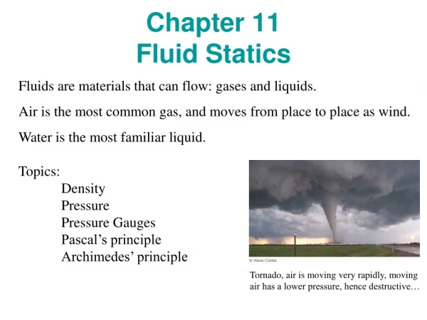
Chapter 2: Fluid Statics Fluid Mechanics Overview Fluid Mechanics Gas Liquids Statics Dynamics , Flows Water, Oils, Alcohols, etc. Stability Air, He, Ar, N2, etc. Buoyancy Pressure Compressible/ Incompressible Laminar/ Turbulent Surface Tension Steady/Unsteady Compressibility Density Viscosity Vapor Pressure Viscous/Inviscid Fluid Dynamics: Rest of Course Chapter 1: Introduction
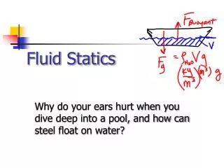
Fluid Statics • By definition, the fluid is at rest. • Or, no there is no relative motion between adjacent particles. • No shearing forces is placed on the fluid. • There are only pressure forces, and no shear. • Results in relatively “simple” analysis • Generally look for the pressure variation in the fluid
Pressure Forces Gravity Force Pressure at a Point: Pascal’s Law Pressure is the normal force per unit area at a given point acting on a given plane within a fluid mass of interest. Blaise Pascal (1623-1662) How does the pressure at a point vary with orientation of the plane passing through the point? Wedged Shaped Fluid Mass F.B.D. • p is average pressure in the x, y, and z direction. • Ps is the average pressure on the surface • q is the plane inclination • is the length is each coordinate direction, x, y, z ds is the length of the plane g is the specific weight V = (1/2dydz)*dx
Rigid body motion in the y-direction Pressure Force in the y-direction on the y-face Pressure Force on the plane in the y-direction Pressure Force in the plane in the z-direction Pressure Force in the z-direction on the z-face Rigid body motion in the z-direction Weight of the Wedge Pressure at a Point: Pascal’s Law For simplicity in our Free Body Diagram, the x-pressure forces cancel and do not need to be shown. Thus to arrive at our solution we balance only the the y and z forces: Now, we can simplify each equation in each direction, noting that dy and dz can be rewritten in terms of ds:
Math Pressure at a Point: Pascal’s Law Substituting and rewriting the equations of motion, we obtain: Now, noting that we are really interested at point only, we let dy and dz go to zero: Pascal’s Law: the pressure at a point in a fluid at rest, or in motion, is independent of the direction as long as there are no shearing stresses present.
Pressure at a Point: Pascal’s Law p1dxds psdxds p2dxds ps = p1 = p2 Note: In dynamic system subject to shear, the normal stress representing the pressure in the fluid is not necessarily the same in all directions. In such a case the pressure is taken as the average of the three directions.
Surface Forces Taylor Series Body Forces Pressure Field Equations How does the pressure vary in a fluid or from point to point when no shear stresses are present? Consider a Small Fluid Element • p is pressure • is specific weight V = dydzdx For simplicity the x-direction surface forces are not shown
Pressure Field Equations Looking at the resultant surface forces in the y-direction: Similarly, looking at the resultant surface forces in the x and z-direction, we obtain: Expressing these results in vector form:
Pressure Field Equations Now, we note by definition, the “del” operator or gradient is the following : Then, Now, rewriting the surface force equation, we obtain the following: Now, we return the body forces, and we will only consider weight:
dm “Most General Form” for No Shear Pressure Field Equations Use Newton’s Second Law to Sum the Forces for a Fluid Element: dm is the mass of the fluid element, and a is acceleration. Then summing the surface forces and the body forces:
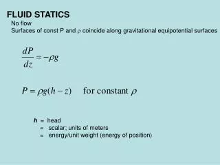
0 Hydrostatic Condition: a = 0 Writing out the individual vector components: This leads to the conclusion that for liquids or gases at rest, the Pressure gradient in the vertical direction at any point in fluid depends only on the specific weight of the fluid at that point. The pressure does not depend on x or y. Hydrostatic Equation
Hydrostatic Condition: Physical Implications • Pressure changes with elevation • Pressure does not change in the horizontal x-y plane • The pressure gradient in the vertical direction is negative • The pressure decreases as we move upward in a fluid at rest • Pressure in a liquid does not change due to the shape of the container • Specific Weight g does not have to be constant in a fluid at rest • Air and other gases will likely have a varying g • Thus, fluids could be incompressible or compressible statically
Hydrostatic Condition: Incompressible Fluids The specific weight changes either through r, density or g, gravity. The change in g is negligible, and for liquids r does not vary appreciable, thus most liquids will be considered incompressible. Starting with the Hydrostatic Equation: We can immediately integrate since g is a constant: where the subscripts 1 and 2 refer two different vertical levels as in the schematic.
Linear Variation with Depth Hydrostatic Condition: Incompressible Fluids As in the schematic, noting the definition of h = z2 –z1: h is known as the pressure head. The type of pressure distribution is known as a hydrostatic distribution. The pressure must increase with depth to hold up the fluid above it, and h is the depth measured from the location of p2. The equation for the pressure head is the following: Physically, it is the height of the column of fluid of a specific weight, needed to give the pressure difference p1 – p2.
p = po h1 p = p1 p = p2 Hydrostatic Condition: Incompressible Fluids If we are working exclusively with a liquid, then there is a free surface at the liquid-gas interface. For most applications, the pressure exerted at the surface is atmospheric pressure, po. Then the equation is written as follows: The Pressure in a homogenous, incompressible fluid at rest depends on the depth of the fluid relative to some reference and is not influenced by the shape of the container. Lines of constant Pressure For p2 = p = gh + po For p1 = p = gh1 + po
Hydrostatic Application: Transmission of Fluid Pressure • Mechanical advantage can be gained with equality of pressures • A small force applied at the small piston is used to develop a large force at the large piston. • This is the principle between hydraulic jacks, lifts, presses, and hydraulic controls • Mechanical force is applied through jacks action or compressed air for example
Note: g = rg and not a constant, then Thus, Then, Hydrostatic Condition: Compressible Fluids Gases such as air, oxygen and nitrogen are thought of as compressible, so we must consider the variation of density in the hydrostatic equation: R is the Gas Constant T is the temperature r is the density By the Ideal gas law: For Isothermal Conditions, T is constant, To:
Hydrostatic Condition: U.S. Standard Atmosphere Idealized Representation of the Mid-Latitude Atmosphere Standard Atmosphere is used in the design of aircraft, missiles and spacecraft. Stratosphere: Isothermal, T = To Troposphere: Linear Variation, T = Ta - bz
Hydrostatic Condition: U.S. Standard Atmosphere Starting from, Now, for the Troposphere, Temperature is not constant: b is known as the lapse rate, 0.00650 K/m, and Ta is the temperature at sea level, 288.15 K. Substitute for temperature and Integrate: pa is the pressure at sea level, 101.33 kPa, R is the gas constant, 286.9 J/kg.K
Measurement of Pressure Absolute Pressure: Pressure measured relative to a perfect vacuum Gage Pressure: Pressure measured relative to local atmospheric pressure • A gage pressure of zero corresponds to a pressure that is at local atmospheric pressure. • Absolute pressure is always positive • Gage pressure can be either negative or positive • Negative gage pressure is known as a vacuum or suction • Standard units of Pressure are psi, psia, kPa, kPa (absolute) • Pressure could also be measured in terms of the height of a fluid in a column • Units in terms of fluid column height are mm Hg, inches of Hg, inches of H20,etc Example: Local Atmospheric Pressure is 14.7 psi, and I measure a 20 psia (“a” is for absolute). What is the gage pressure? The gage pressure is 20 psia – 14.7 psi = 5.3 psi If I measure 10 psia, then the gage pressure is -4.7 psi, or is a “vacuum”.
+ - + + Measurement of Pressure: Schematic
Note, often pvapor is very small, 0.0000231 psia at 68° F, and patm is 14.7 psi, thus: Measurement of Pressure: Barometers The first mercury barometer was constructed in 1643-1644 by Torricelli. He showed that the height of mercury in a column was 1/14 that of a water barometer, due to the fact that mercury is 14 times more dense that water. He also noticed that level of mercury varied from day to day due to weather changes, and that at the top of the column there is a vacuum. Evangelista Torricelli (1608-1647) Schematic: Torricelli’s Sketch Animation of Experiment:
Measurement of Pressure: Manometry Manometry is a standard technique for measuring pressure using liquid columns in vertical or include tubes. The devices used in this manner are known as manometers. • The operation of three types of manometers will be discussed today: • The Piezometer Tube • The U-Tube Manometer • The Inclined Tube Manometer The fundamental equation for manometers since they involve columns of fluid at rest is the following: h is positive moving downward, and negative moving upward, that is pressure in columns of fluid decrease with gains in height, and increase with gain in depth.
Measurement of Pressure: Piezometer Tube po Disadvantages: 1)The pressure in the container has to be greater than atmospheric pressure. 2) Pressure must be relatively small to maintain a small column of fluid. 3) The measurement of pressure must be of a liquid. Move Up the Tube Closed End “Container” pA (abs) pA(abs) - g1h1 Moving from left to right: = po Rearranging: Gage Pressure Then in terms of gage pressure, the equation for a Piezometer Tube: Note: pA = p1 because they are at the same level
Measurement of Pressure: U-Tube Manometer Note: in the same fluid we can “jump” across from 2 to 3 as they are at the sam level, and thus must have the same pressure. The fluid in the U-tube is known as the gage fluid. The gage fluid type depends on the application, i.e. pressures attained, and whether the fluid measured is a gas or liquid. Closed End “Container” pA Since, one end is open we can work entirely in gage pressure: pA - g2h2 Moving from left to right: + g1h1 = 0 Then the equation for the pressure in the container is the following: If the fluid in the container is a gas, then the fluid 1 terms can be ignored:
Measurement of Pressure: U-Tube Manometer Measuring a Pressure Differential Closed End “Container” pB Final notes: 1)Common gage fluids are Hg and Water, some oils, and must be immiscible. 2)Temp. must be considered in very accurate measurements, as the gage fluid properties can change. 3) Capillarity can play a role, but in many cases each meniscus will cancel. Closed End “Container” pA - g3h3 pA = pB + g1h1 - g2h2 Moving from left to right: Then the equation for the pressure difference in the container is the following:
l2 h2 q q Measurement of Pressure: Inclined-Tube Manometer This type of manometer is used to measure small pressure changes. pB pA h2 - g3h3 pA = pB + g1h1 - g2h2 Moving from left to right: Substituting for h2: Rearranging to Obtain the Difference: If the pressure difference is between gases: Thus, for the length of the tube we can measure a greater pressure differential.
Measurement of Pressure: Mechanical and Electrical Devices Spring Bourdon Gage: Diaphragm: