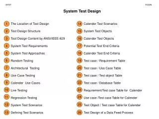
Comprehensive Testing and Verification of Petals, Interconnect Boards, and Control Links
This document details the design and verification processes for petals and interconnect boards, focusing on mechanics, electrical performance, and thermal behavior. It outlines tests for different detector groups, assessing mechanical compatibility with petal structures, fixation points, and electrical performance including quality of production, insulation testing, and power distribution. Tools used include dummy loads, test systems, and control link verification to ensure proper operation. Noise studies and grounding issues are also addressed.

Comprehensive Testing and Verification of Petals, Interconnect Boards, and Control Links
E N D
Presentation Transcript
System Test 2002 • Design verification of petals and interconnect boards and control links without detectors • mechanics • electrical performance • thermal behavior • Test of the IInd detector group (rings #3, #4, #6) • ring #6 full equipped with Si-Modules ,and optical hybrids • ring #3 and #4 ‚ equipped with detector frames, frontend hybrids and • optical hybrids only • Test of the IIIrd detector group (rings #5, #7) • equipped with detector frames , frontend hybrids and optical hybrids only • Test of the Ist detector group (rings #1, #2) • equipped with detector frames , frontend hybrids and optical hybrids only
Mechanics • mechanical compatibility of the InterConnect Boards (ICB) with the mechanical structure of petals • fixation points, inserts and holes for alignment system • position of the FE hybrid connectors vs. position of the detector modules, mech. stress of the Detector Module • fixation of the optical hybrids and routing of the fibers • mechanical stress of the ICB, cable connectors, ends of multiservice cables • due to the plugging and unplugging of multiservice cables • due to current flow in magnetic field, if the petals are tilted a little bit • dynamic stress on the non twisted cable ends due to switching on and off of groups of FE Hybrids, • due to the large thermal expansion coefficient of pcb material and large difference in two operating conditions –30 °C and room temperature
Equipment: • Magnetic field, B 1Tesla (Bonn or CERN) • Switchable dummy load of Frontend Hybrid • dummy load of Optical Hybrid • Thermo – Vacuum chamber
Electrical performance • Quality of production • continuity of connections, • insulation test of HV-distribution • test system for mass production of assembled ICB • Power distribution • voltage drops; verification of x-section of power lines • verification of points of attachment of sense wires and ground reference • measurement of the over-voltage (due to switching off/on of the FE hybrids and inductance of the long cables) as a function of capacitive load, protection against over-voltage? • location of the capacitors on the ICB, total capacitance on the ICB
Electrical performance (cont.) Signal Integrity of the distribution of the fast control signals: clock, reset and back plane pulses
Connection Test System Technical data Test points: 64 - 4096 Low voltage: 0,1 - 40VDC Insulation test: 50 - 1500 VDC Test current: 50 mA - 2 A Selective component test Resistors Capacitors Diodes / Zener diodes Costs: Frame : 12 000 € 64 test points module: 500 € total for 2048 test points: 28 000 €
Connection Test System based on CCUM • Dummy of FE - Hybrid eqipped with I2C controlled 16 BIT I/O port • and a little logic to test the voltage level on each pin of connector • Dummy of OH with a little logic to test the voltage level on each pin of connector
Tools for the test of power distribution and Signal Integrity • „Emulator“ of the CCUM with the basic functions
Tools for the test of power distribution (cont.) • Switch-able dummy load of Front-end Hybrid • dummy load of Optical Hybrid • both with the proper dynamic resistivity of the power ports Schematics of the dummy
Control link and control optoelectronics on the level of petals • mechanical verification of the control ring • fixation of the digital optical hybrids (DOH), fixation of the CCUMs • cable routing • Cooling of the DOH module • verification of the electrical performance of control ring • impedance matching, termination, reflections • shielding of cables, shielding of DOHs • voltage margin, cross section of power lines and GND lines • verification of grounding concept, bit error rate • verification of redundancy of control link
Tools for Tests of Control link • 1 stage • CCUM 2 pc/petal, • FEC 1 pc • Front-end hybrids or few • dummies with I2C I/O Port 4-11 pc • 2 stage • 1 control link 6 CCUMs (3) • ICB for IInd group 3pc • Inter-petal cables 3 pc • FEC 1 pc • dummies with I2C I/O Port 12-33 pc • 3 stage • Optical link 1 pc • Digital Optical Hybrid 2 pc/control link • ICB for IInd group 3pc • Inter-petal cables 3 pc • dummies with I2C I/O Port12-33 pc
Noise studies with Si-Detectors of II detector group • Pick up from digital signals • Ground loops, grounding of frames • Noise from cooling system if any? • Studies of shielding requirements of petals • Influence of ripples on the supply voltage to the quality of APV readout • Common mode effects at the level of power groups ; can noise from crazy chips feed through the power lines to other chips.
Required readout electronics Services LV – Power Supplies : HP E3633A + HP E3614A HV – Biasing: EHQ 8006F, 8 isolated channels, 600V, noise =2 mVpp, I resolution =100pA Temp Control: Keithley 2700 DAQ