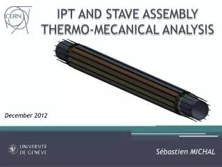
IPT AND STAVE ASSEMBLY THERMO-MECANICAL ANALYSIS
590 likes | 786 Vues
IPT AND STAVE ASSEMBLY THERMO-MECANICAL ANALYSIS. OBJECTIVE. This analysis has been performed to check the thermo-mechanical behavior during the different running phases of the IBL experiment: Bake-out Cooling only Running mode A steady state analysis is used as input for the structural

IPT AND STAVE ASSEMBLY THERMO-MECANICAL ANALYSIS
E N D
Presentation Transcript
OBJECTIVE • This analysis has been performed to check the thermo-mechanical behavior during the different running phases of the IBL experiment: • Bake-out • Cooling only • Running mode • A steady state analysis is used as input for the structural analysis of the complete assembly • The same analysis is used as to check the displacement of the IPT and the staves independently in order to compare their relative displacements
IBL PACKAGE Z0 SECTION IST BP IPT
MODEL • Only mechanical structures are considered • Beam pipe in contact with beam pipe rings • Beam pipe ring in contact with IPT IPT Beam pipe rings End of Stave rings IST Beam pipe contacts
Thermal Inner Positioning Tube • 5 layers K13C (-20/20/90/20/-20) • https://edms.cern.ch/file/1229693/1/carbon_catalog.pdf • Tencate RS3 cyanate-esther matrix • https://edms.cern.ch/file/1229691/1/RS-3_TB_DS_Web.pdf • Material properties thanks to Colin DALY / Henry LUBATTI
Structural Inner Positioning Tube • 5 layers K13C (-20/20/90/20/-20) • https://edms.cern.ch/file/1229693/1/carbon_catalog.pdf • Tencate RS3 cyanate-esther matrix • https://edms.cern.ch/file/1229691/1/RS-3_TB_DS_Web.pdf • Solid element with layering capability
Beam Pipe / Beam Pipe rings • Beam pipe made of berylium • Beam pipe rings and pins made of Vespel contact
End of Stave rings • Made of CFRP using a quasi-isotropic layup • Bonded to the IPT • Material properties thanks to Colin DALY / Henry LUBATTI
IBL stave assembly Omega Flex Cooling pipe End block Stave foam (6x) Face plate End block
OMEGA / FACE PLATE • 3 layers K13C (0/90/0) • Tencate RS3 matrix • Equivalent material properties based on composite-pro software
STAVE FOAM • K9 carbon fiber foam • https://edms.cern.ch/document/1229761/1
THERMAL ANALYSIS: BAKE OUT BAKE OUT • Steady state analysis (no convection) • Model of IBL central section with EoSrings and staves, 900 mm long • 3 different configurations: • Bake-out • Outer BP surface temperature of 250°C • Inner cooling pipes surface temperature of -35°C • IST outer surface at 10°C with a film convection coefficient of • Cooling only • IST outer surface at 10°C with a film convection coefficient of • Adiabatic behavior of the beam pipe inner surface • Inner cooling pipes surface temperature of -35°C • Standard running mode • Inner cooling pipes surface temperature of -35°C • Heat flow of per stave face plate ( total) • Heat flow of per flex ( total) • IST outer surface at 10°C with a film convection coefficient of • Adiabatic behavior of the beam pipe inner surface • No aerogel insulation on BP • Only mechanical structures (no sensors on staves)
THERMAL RESULT BAKE OUT T=-35°C T=250°C • Temperature overall distribution T=10°C
THERMAL RESULT BAKE OUT BP RING End of Stave Ring BP • Temperature overall distribution IPT Stave (x14)
THERMAL RESULT BAKE OUT • BP ring temperature distribution • 250°C at BP contact location • 103°C on top
THERMAL RESULT BAKE OUT • IPT temperature distribution • -10°C below the EoS rings • 135°C at the BP rings pads contact location
THERMAL RESULT BAKE OUT • EoStemperature distribution • -30°C below the end blocks • 10°C on the IPT
THERMAL RESULT BAKE OUT • Stave temperature distribution • -3°C on the stave end blocks
THERMAL CONCLUSION BAKE OUT • Previous 2D CFD analysis showed a maximum temperature of the IPT at 76 °C in bake-out configuration: https://indico.cern.ch/conferenceDisplay.py?confId=204193 • This analysis was a 2D section at Z=0 with BP in nominal position: • No heat flux between BP and IPT through BP rings during bake-out. • No heat flux between the IPT and the staves through the EoS rings. • In the current thermo-mechanical analysis, the temperature of the IPT at Z=0 is between 47°C and 57°C.
IPT / STAVES EXPANSION • The result of the thermal analysis has been used as input to calculate the thermal expansion: • the IPT with the EoS rings • the 14 staves assembly In order to check the length variation between those components. • The corresponding reaction forces will be studied in the complete assembly static structural analysis (slide 22)
SINGLE IPT BAKE OUT • By using the IPT temperature of the complete assembly (slide 12), it contracts by 10 µm Fixed 1e-2 mm Simply supported
SINGLE STAVES BAKE OUT • By using the temperature of the complete assembly (slide 12), the staves themselves contracts by 35 µm Simply supported Fixed ~35 µm The relative displacement btw staves and IPT in this thermal configuration at the EoS ring is around 0.025 mm
STRUCTURAL ANALYSIS BAKE OUT • Result of previous steady state thermal analysis used as input • Standard earth gravity along –Y axis included • Same model of thermal IBL central section but without IST, BP and BP rings. • Boundary conditions: • Fixed on the bottom face of bottom end block side A • Simply supported on the bottom face of bottom end block side C
STRUCTURAL RESULT BAKE OUT • Total deformation: 0.3 mm • Deformation along Y axis: 0.3 mm
STRUCTURAL RESULT BAKE OUT • EoS ring • Von Mises stress: 41 Mpa • Maximum displacement: 0.05 mm • Maximum displacement along X axis: 0.03 mm
STRUCTURAL RESULT BAKE OUT • IPT thin section • Max total displacement: 0.04 mm • Max displacement along Y axis: 0.02 mm
STRUCTURAL RESULT BAKE OUT • IPT thin section • Tsai-Wu Failure criteria
STRUCTURAL RESULT BAKE OUT • Tsai-Wu failure criterion for IPT layer 2= 0.4
STRUCTURAL RESULT BAKE OUT • Tsai-Wu failure criterion for IPT layer 3= 0.4
STRUCTURAL RESULT BAKE OUT • Tsai-Wu failure criterion for IPT layer 4= 0.5
STRUCTURAL RESULT BAKE OUT • Tsai-Wu failure criterion for IPT layer 5= 0.5
STRUCTURAL RESULT BAKE-OUT • Interlaminar shear stress below 5 MPa.
THERMAL ANALYSIS:COOLING COOLING ONLY • Boundary conditions: • All bodies' temperature at -35°C • IST outer surface at 10°C with a film convection coefficient of • Adiabatic boundary condition on BP inner surface T=-35°C T=10°C Inner BP surface adiabatic
IPT / STAVES EXPANSION COOLING ONLY • The result of the thermal analysis has been used as input to calculate the thermal expansion: • the IPT with the EoS rings • the 14 staves assembly In order to check the length variation between those components. • The corresponding reaction forces will be studied in the complete assembly static structural analysis (slide 22)
SINGLE IPT COOLING ONLY • By using the IPT temperature of the complete assembly (slide 31), it expends by 15 µm -15e µm Simply supported Fixed
SINGLE STAVES COOLING ONLY • By using the temperature of the complete assembly (slide 31), the staves themselves contracts by 53 µm Simply supported ~3e-2 mm Fixed The relative displacement btw staves and IPT in this thermal configuration at the EoS ring is around 0.07 mm
STRUCTURAL ANALYSIS COOLING ONLY • Result of previous steady state thermal analysis used as input • Standard earth gravity along –Y axis included • Same model of thermal IBL central section but without IST, BP and BP rings. • Boundary conditions: • Fixed on the bottom face of bottom end block side A • Simply supported on the bottom face of bottom end block side C
STRUCTURAL RESULT COOLING ONLY • EoS ring • Maximum displacement: 0.08 mm • Von Mises stress: 50 MPa
STRUCTURAL RESULT COOLING ONLY • IPT thin section • Maximum displacement: 0.2 mm
STRUCTURAL RESULT COOLING ONLY • IPT thin section • Tsai-Wu Failure criteria
STRUCTURAL RESULT COOLING ONLY • Tsai-Wu failure criterion for IPT layer 2= 0.3
STRUCTURAL RESULT COOLING ONLY • Tsai-Wu failure criterion for IPT layer 3= 0.25
STRUCTURAL RESULT COOLING ONLY • Tsai-Wu failure criterion for IPT layer 4= 0.3
STRUCTURAL RESULT COOLING ONLY • Tsai-Wu failure criterion for IPT layer 5= 0.3
STRUCTURAL RESULT COOLING ONLY • Interlaminar shear stress below 8 MPa.
REACTION FORCES COOLING ONLY • The force between a stave and the ring is between 50 and 70 N along the Z axis (IPT axis) depending on the temperature distribution. • The total force along the z axis is equal to
THERMAL ANALYSIS: RUNNING RUNNING • Boundary conditions: • Inner cooling pipes surface temperature of -35°C • Heat flow of per stave face plate ( total) • Heat flow of per flex ( total) • IST outer surface at 10°C with a film convection coefficient of
THERMAL RESULT RUNNING T=-35°C • Temperature overall distribution T=10°C on face plate
THERMAL RESULT RUNNING End of Stave Ring • Temperature overall distribution IPT Stave (x14)
THERMAL RESULT RUNNING • Stave temperature overall distribution IBL stave temperature distribution by Mauro MONTI January 2011 EDMS ATL-IP-EA-0003