Design
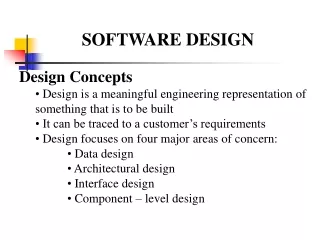
Design. Designing is the creative activity of transforming the requirements into solutions The description of the solution is called the design and it is captured in a design document While creativity is very difficult to describe and teach, we can discuss it .

Design
E N D
Presentation Transcript
Design • Designing is the creativeactivity of transforming the requirements into solutions • The description of the solution is called the design and it is captured in a design document • While creativity is very difficult to describe and teach, we can discuss it. The text book chapters 5&6 and my slides “combined” should help
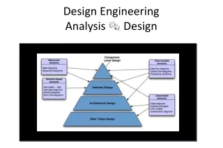
Major Conceptual Tools used in Design • Abstraction: a representation of the “essentials” of something, with the details removed to allow the coping with and lessening of complexity • Synthesis: a combination of smaller, simpler parts into a larger component, dropping duplicationsand improving performance • Decomposition : a breakdown of a component into smaller and simpler sub-components, with more details shown at each lower level of decomposition. Each of these may provide a slightly different “view”
How Do We Start the “Design” • There is a time when everything seems fuzzy and you need all 3 activities: abstract, synthesize, and decompose.There is no simple “prescirption” to follow. Where do we start from? • Look at (think about) the requirements and use it to identify “key functional” components. • look at main scenarios (both normal and error) • Consider the relationships among these components. • STOP and draw a “picture”; step back • Try some more scenarios from the requirements ---- make some changes • Consider the non-functional constraints e.g. performance
Several Potential Sources of Design Guidance Similar Systems Past Experience Reference Model Design Design Principles Architectural Styles Design Patterns Design Conventions
2 Levels of Designs • Conceptual Design (closer to requirements) Document: • Describes the functionality and characteristics of the solution system in a manner that the customers andusers canunderstandand can respond. • It describes a lot of the “what” of the solution • what are the incoming data and what is the format • what happens to the incoming data • what major functions will process the data • what does the user have to perform • what are the system interfaces and what do they look like • what are the user interfaces and what do they look like • what is done to achieve the performance and availability targets of the system
2 Levels of Design (cont.) • Technical Design (closer to design) Document: • Describes the functionality and the characteristics of the solution system for the system builders and implementers to understand and respond. • It describes a lot of the “how” of the solution • how does the data get captured and inputted • how is the data structured and processed along with which functions process it. • how would the users perform his or her functions • how do the system interfaces interact with each other and with what information • how do the user interfaces interact with system and the users and how are they created • how the system performance and availability functions are implemented
High Level Design (Architecture) • Often we have one High Level Design document for both the conceptual and technical designs • describes the majorhardware, software, and humancomponents and their : • individual attributes and what functions they “intend to perform” • their relationships to and interfaces with each other • control • data • describes the major system input and output : • data format • timing and performance • describes the major user interfaces: • basic paradigm (e.g. menu driven, domain specific based, etc.) • size, format, defaults, etc. • required interactions with users
A Simple High Level Design Example • The “Power” Function (y = xb) Design: • Major Components: • hardware: any PC with 64 meg main memory and 1 gig storage, screen monitor, mouse, and keyboard, runs MS Windows, etc. • system software: MS Windows operating system • * application software* : Power Function application (more later) • user : interactive with the application through both mouse and keyboard to input the number and the power or to respond to the messages from the system. • “System” Input and outputs: • none between operating system and “Power” application except the I/O from the Power application (written some high level language) to the screen. • application will be stored on the C-drive via the user directory
Major “layered” ComponentsExample (continued) Application Software – “Power Function” Operating System (MS Windows version xx) PC Hardware (64 meg; 1 gig storage; keyboard; display screen; etc.)
Simple High Level Design Example (cont.) • The (*Application Software*)“Power” function software will have three main sub-components: • input data validation • process the power function • display the output and messages • These three main “sub-components” interact as follows: • All input data will be validated by the input data validationsub-component. There are 2 input data: 1) the number and 2) the power. These two integers’ - size and type - will be validated and any message will be sent to the output display sub-component. Valid input will be sent to the power processing sub-component for processing. • Power process sub-component will receive the inputs from the input validation sub-component and compute the power. The result of the computation will be sent to the outputdisplay sub-component to be displayed on the screen
Simple High Level Design Example (cont.) 3. Display and output sub-componentwill receive inputs from other sub-components, directing it to display the appropriate messages and outputs.
High Level Component Design Diagram Components (1),(2) and (3) are described earlier ; what about UI? (1) U. I. Input Accepting and Validation (Validated input) User (Error messages) (2) Process the Power Function (Valid output) or Display the messages & output (3) (Error message)
Simple High Level Design Example (cont.) 3. User Interface will be divided into two major types: • User input: • labeled input fields for the two positive integers (number and the power) with default set at integer 0. • An O.K. button to trigger the processing • A Terminate button to terminate the function completely • Outputs: • labeled output field showing the result from processing the power • labeled message field for any error messages on input or processing • An Input Again button to trigger the input interface • A Terminate button to terminate the function completely You may show the actual screen layout with this ---- that would be even better!
Reminder on Conceptual DesignTools • In the design example we used all three concepts: • Abstraction of the Power Function (e.g. never discussed the actual algorithms nor the implications of negative power and imaginary number) • Decomposition of the Application Power function into three major sub-components, showing more details at the sub-component level, along with showing the interrelationship among the sub-components • Synthesis of each of the three sub-component, which performs its own specialized function, with as little duplication as possible -- together they satisfy the requirement; UI (with screens) would be further synthesis
Detailed Design • The High Level Design leaves too much choices and allows too much inventions by the programmers, thereby decreasing the chance of meeting the requirements. • More Detailed Design is needed. • Decomposition of the Higher Level Design is needed • ** The decomposition process should be carried to the level such that the lowest level allows the programmers to design and write the program module. ** • A Well Defined Detailed design describes • (1)all and only the necessary inputs, • (2)the actual function, and • (3)all the outputs created by the function and no more
Wasserman’s Suggested Design Decompositions • Modular Decomposition - a functional decomposition & featured orienteddecomposition into sub-functions such that at each level of decomposition the functional descriptions are more and more detailed • Data Oriented Decomposition - a data structural decomposition where the data structure is first described and each lower level of decomposition describes the inner data structure until every data element is described in terms of its type, format, default value, etc.
Wasserman’s Suggested Design Decompositions (cont.) 3. Event Oriented Decomposition- a description ofall external and internal events that change the states of the system; each change of state is coupled with lower level descriptions of the evoked activities or functions. 4. Outside-in Design- similar to event oriented decomposition with user input as events - - -(very suitable for web applications) • Object Oriented Design- an abstraction ofclasses followed by more detailed descriptions of the attributes of the classes and relationships among classes. • Process Oriented Decomposition– partitioning the system into execution processes (e.g. parallel and coordination)
End of Detailed Design • What characterize the “end” of detailed design? • The design has been decomposed to the level where the independent units are each equivalent to a “compilable” programming module. ( how does this apply to an HTML document that triggers a “program”?) • The key algorithms have been described to the level where the transformation into the programming code is only the effort of transforming into the chosen specificprogramming language constructs. (e.g. note that some programming language contain constructs which may influence the algorithm .) • Data structures must also be described to the programmable level (note that programming languages’ data facilities, such as string or stack, may also influence the data structure design); for db, to the table level
Some High Level Design and Architecture “Styles” • Design involves creativity and also some styles. • Some existing styles, of different acceptance and popularity are : • Object Oriented (currently popular - complete methodology) • Client-Server ( was commercially popular - systems architecture) • Layering (an architecture style) • Central Repository (an architecture style) • Pipes and filters ( an architecture/ design style) • Event Driven Invocation (a modeling and design style) • Interpreters (a conceptual style) • Real-time and Process control (a domain specific design – closer to reference model) • These styles are not exclusive of each other. One may mix some of the styles.
Object Oriented Design – (Methodology) • Currently, a very popular style of design, involving the following major concepts: • Class or objects : an abstraction of an entity that contains both the data structure of the entity and the functions (called methods) that the entity may perform. Envisioning the solution with a set of inter-related classes is the “key” to OO design. • Encapsulation: information may be hidden within the class so that other classes do not have to deal with the complexity of the innards of the class; inter-class communication is done via “messages” • Inheritance: classes can be “reused” via inheritance of both the data structures and the methods by other sub-classes.
OO Class Design Representations A class is composed of 3 parts : - class name - class attributes specifying the data - class methods specifying the functions Class Name Class Attributes Class Methods Another class may inherit attributes and methods from a class Sub-Class Name Sub-Class Attributes Sub-Class Methods
OO Interaction Design (Sequence Diagram) Object 1 Object 2 Object 3 Invokes an object 2 method Invokes an object 3 method Return
Client Server Architecture Design • This design style became popular with the advent of PC and the decentralization of large central computer. • It is based on the concept of splitting the functions which resided in one central computer into parts so that some functions are performed at the PC and controlled by the PC. • The first iteration of this design (fat client) placed major application functions at the PC and most of the database functions at a central server. • The application design was still not simplified much, but the middle-ware and development tools simplified the system design.
DB DB Sample Client Server Architecture(s) Server DB Server Application Severs Thin Client Thin Client Fat Client Fat Client Fat Client Thin Client Fat Clients Thin Clients
DB Today’s Distributed Internet Architecture Application Server(s) DB Server(s) Network Server(s) Internet Client Client
Client Server Architecture • Client-Server architecture only provides a “splitting” architecture of the application system components, not quite of the application logic itself: • Presentation Services • screen • reports • Data Base • Applications Logic • Network Services • Design of the actual application solution isstill needed (including how you want to “split” the application). Software: 1)Peer-Peer architecture & 2) Publish-Subscribe architecture
Layering Architecture • Layers are hierarchical, with each layer providingservice to the immediate higher (outer) layer and receives services from the immediate lower (inner) layer. • The communications (evocation and data passing) across layers are defined and must be strictly followed. • There are two well-known models of layering architecture : • communications and network software • overall software on top of the hardware
Layering Architecture Example The application is separate from OSI Applications Layer - Services provided to present the data for viewing, printing, etc. Layer 6 Presentation Services Layer - Services provided to keep two applications in session to exchange data Layer 5 Session Services Layer - Services provided to move packets from one station to another in a network Layer 4 Transport Services Layer Layer 3 Network Services Layer - Services provided as interface between the data link and the transport layer Layer 2 Data-Link Protocol Layer - Services provided to move information across the physical layer (or across net-nodes) Layer 1 Physical Layer - Hardware and software facilitating the actual movement of stream of data on the wire (really no physical for wireless) ISO’s Open System Interconnect (OSI) Model
Operating System Example of Layered Style Applications Programs Operating System Services print “ Hi” Hardware Interrupts & Kernel Services process scheduler printer service HP Device I/O Cross layer Within layer
Central Repository Architecture Style • The concept in Central Repository is to use a single file or a data base table as “the” means to communicate among parts of the applications component. • A Central File or A set of Tables in a DB where information is shared is the central repository • The state of the information in the central repository provides the control among the application components • Application components know what to write and how to interpret the information in the central repository *** One of the most heavily used architecture for commercial applications
Shared-State or Shared-Data Style Independent components or programs interact through shared “global” data Blackboard (may act as active triggers for processing) Repositories (passive ) This style is used in many commercial systems that has a “centralized”database Strongly Data Coupled ! a) Risks? b) Advantages? Component A Component D Shared Data Component B Component E Component C
Central Repository Architecture Examples • In earlier days when there was no database or sophisticated database triggers, file, such as the personnel file, served as the central repository where control information were kept. Each component will interrogate the central repository for the control information or a scan program will scan through the central repository and trigger the appropriate components for processing. • (e.g. master customer file in BCBS) • (e.g. More modern example is the integrated development system where a configuration management DB serves as the central repository )
Pipes and Filters “Design” Style • This style is to show two standard processing parts, extremely suited for “batch” processing: • input and out stream of data called pipes • processing of the data called filter • The actual breakdown, organizationof andsequences of filters are the key to the design activities. Filter 1 Filter 2 Filter 3
Dataflow Style Separate, independent components or programs are executed in some sequential order as data is passed through them to be processed Batch sequential processing Pipe and Filter (data flows through pipe to be processed by filter) Region A daily transactions Sorted Master File sorted daily transactions update Master file Region B daily transactions sort/merge by accnt. # Region C daily transactions these “transactions” may be credit cards, stocks, etc. --- advantage/disadvantage?
Other Styles • Event Driven and triggerscomes in two forms: • a broadcast of an occurrence of an event to all the components, and the components may associate a procedure with that event. (The components all have pre-registered for the events that they have procedures for. ---- like the “Publish-Subscribe” ) • an event triggers some control flag which all the other components checks from time to time • The one potential drawback is the timing of the procedure which responds to the trigger may be “late.”
Other Styles (cont.) • Real-time and Process Control (like event driven): • timing is extremely important • thresholds settings are important in that these thresholds are the predicates for processing logic. (e.g. steam pressure > x, open valve z)
Sense-Compute-Control(Real-time & Event Driven) • Sense-Compute-Control is an architecture which is composed of: • Sensors which sends information from various sources • Compute component which receives the information from sensors and performs all the necessary numerical and logical computations and the sends the result as signals to the Control • Control which receives the results of the computation from the compute component and decides how to control the various devices. • This is an architectural pattern often used in embedded systems. Compute control B sensor 1 control C sensor 2 control D sensor 3 control A Even though arrows go from sensors to compute, it could be ‘compute” polling the sensors.
Today’s Popular Style with JSPfor dynamicpresentation content 1 JSP Browser 4 Data Base/ enterprise system 2 3 Java Bean (Simplemodel - more complex JSP) Servlet (controller) 1 2 Data Base/ enterprise system 4 Browser 3 Java Bean (model) JSP (view) 5 6 Model-View-Controller (MVC)style - separate controller from view)
Multiple Modeling or Describing an Architecture • Decomposition View – breaking into parts • Dependency View – interrelationship among parts • Generalization View – abstraction and grouping • Execution View – execution flow and connectors • Implementation View – code grouping such as modules • Deployment View – execution of computing resources • Work Assignment View – decompose and assign to workers (I do not consider this last one a model of architecture)
A Reminder for Designers • Regardless of the design style one must have answered all the requirements described in the six categories: • Application Functions • User Interface • Application Non-Functions • Business Process • Data and Information • Existing system and systems interfaces • Depending on the amount of requirements expressed and emphasized in each of the six categories, one may choose one style over another